Hawkworks.net main page
Manual main index
| SERVICE INFORMATION | 10-1 |
| TROUBLESHOOTING | 10-1 |
| CYLINDER | 10-2 |
| PISTON | 10-3 |
| PISTON RING INSTALLATION | 10-5 |
| PISTON INSTALLATION | 10-5 |
| CYLINDER INSTALLATION | 10-5 (page number corrected) |
Unit: mm (in)
| ITEM | STANDARD | SERVICE LIMIT | ||
| Cylinder | I.D. | 79.000-79.015 (3.1102-3.1108) | 79.05 (3.112) | |
| Warpage across top | — | 0.10 (0.004) | ||
| Taper | — | 0.06 (0.002) | ||
| Out-of-round | — | 0.06 (0.002) | ||
| Piston, piston rings and piston pin | Piston ring-to-ring groove clearance | TOP | 0.025-0.055 (0.001-0.002) | 0.11 (0.004) |
| SECOND | 0.015-0.045 (0.0006-0.0018) | 0.10 (0.004) | ||
| Ring end gap | TOP | 0.20-0.35 (0.008-0.014) | 0.65 (0.026) | |
| SECOND | 0.35-0.50 (0.014-0.020) | 0.65 (0.026) | ||
| OIL | 0.20-0.80 (0.008-0.031) | 0.95 (0.037) | ||
| Piston O.D. | 78.970-78.990 (3.1086-3.1098) | 78.92 (3.107) | ||
| Piston pin bore | 20.002-20.008 (0.7874-0.7877) | 20.018 (0.7881) | ||
| Connecting rod small end I.D. | 20.016-20.034 (0.7880-0.7887) | 20.04 (0.789) | ||
| Piston pin O.D. | 19.994-20.000 (0.7871-0.7874) | 19.984 (0.7867) | ||
| Piston-to-piston pin clearance | 0.002-0.014 (0.0001-0.0006) | 0.034 (0.0013) | ||
| Cylinder-to-Piston clearance | 0.010-0.035 (0.0004-0.0014) | 0.13 (0.005) | ||
| Piston pin-to-connecting rod small end clearance | 0.016-0.040 (0.0006-0.0016) | 0.060 (0.0024) | ||
Low or uneven compression
Excessive smoke
Overheating
Piston noise
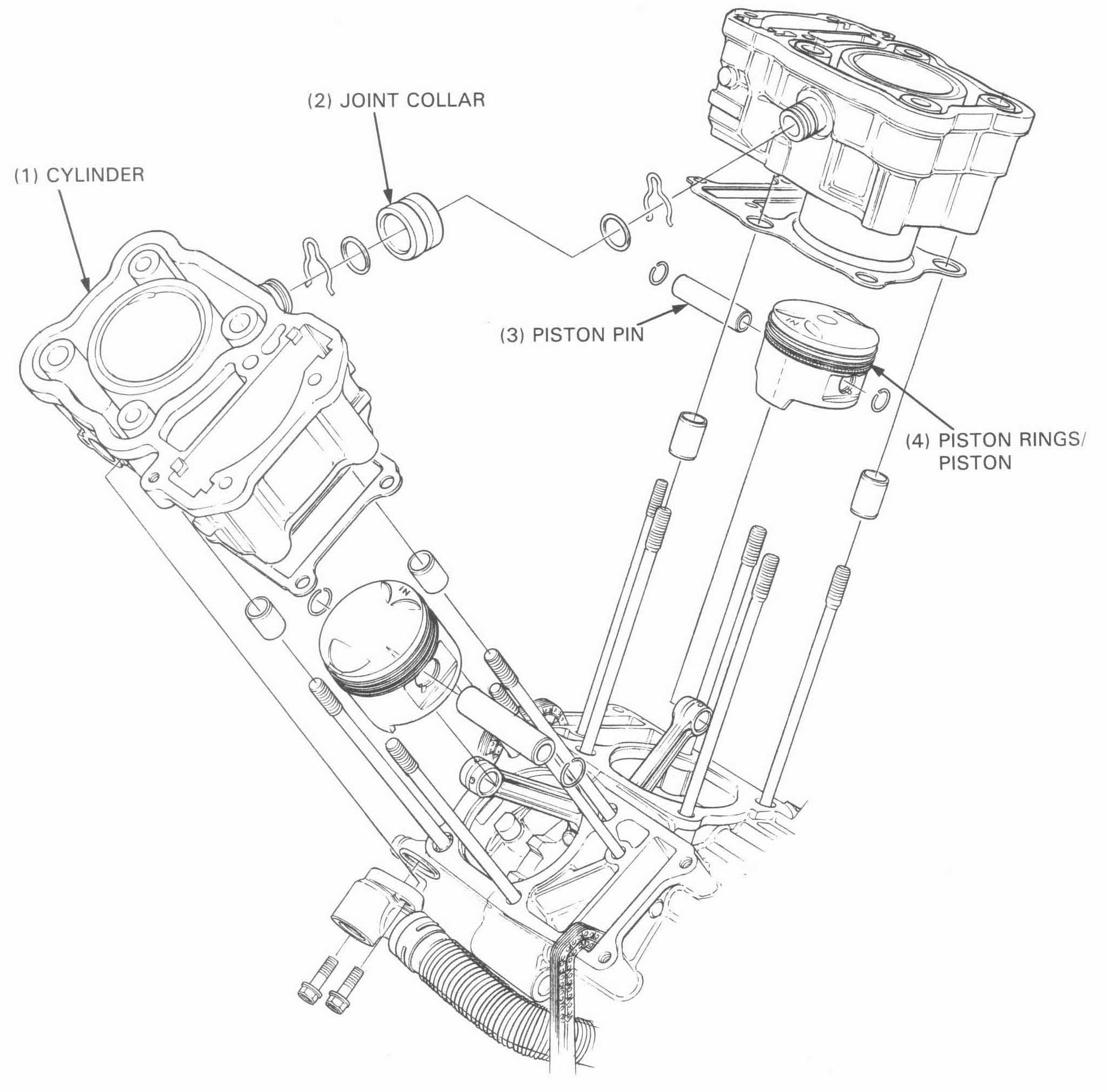
REMOVAL
Remove the following:
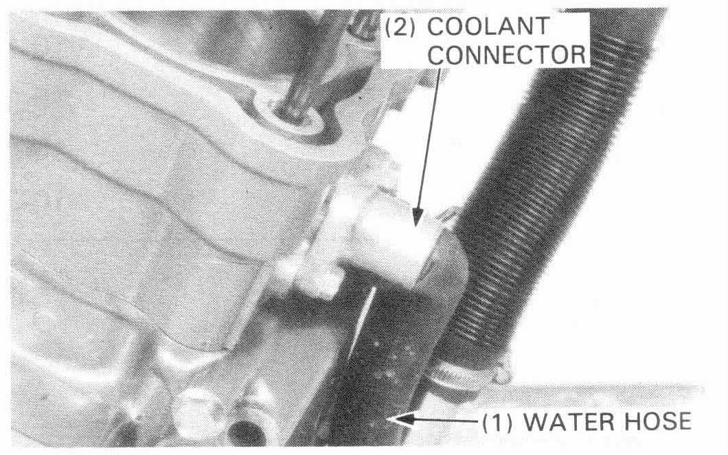
Disconnect the water hose from the coolant connector.
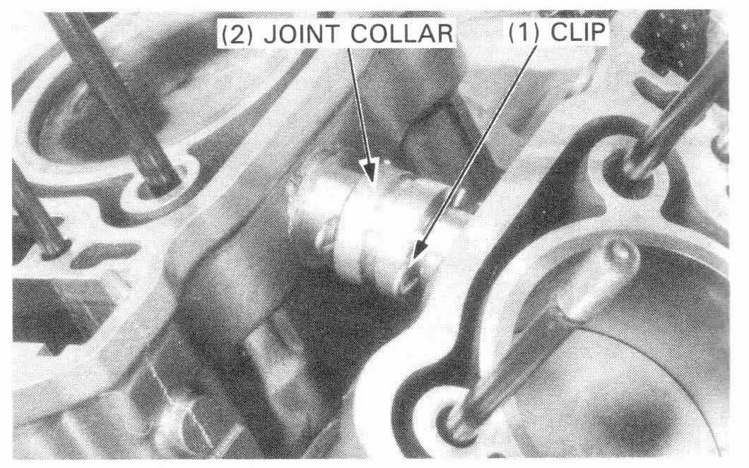
Remove the clip and slide the cylinder joint collar toward either the front or rear cylinder.
Remove the cylinder to be serviced.
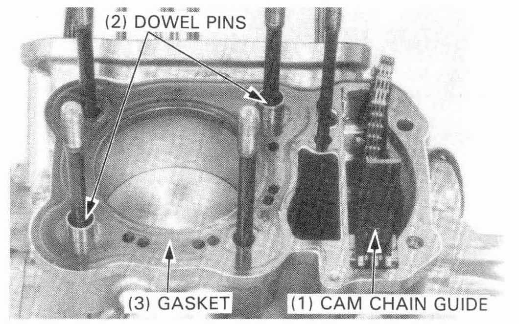
Remove the cylinder gasket and dowel pins from the crankcase.
Clean the top of each cylinder thoroughly.
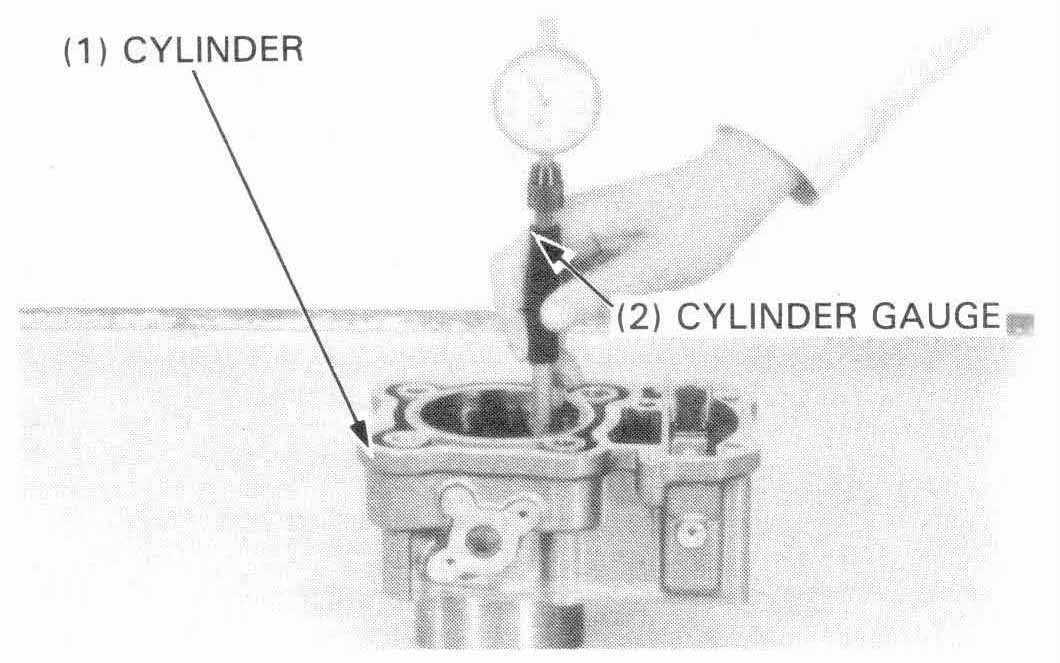
Inspect the cylinder walls for scratches and wear.
Measure and record the cylinder I.D. at three levels in both an X and Y axis. Take the maximum reading to determine the cylinder wear.
SERVICE LIMIT: 79.05 mm (3.112 in)
Calculate the piston-to-cylinder clearance. Take the maximum reading to determine the clearance.
SERVICE LIMIT: 0.13 mm (0.005 in)
Calculate the cylinder for taper at three levels in an X and Y axis. Take the maximum reading to determine the taper.
SERVICE LIMIT: 0.06 mm (0.002 in)
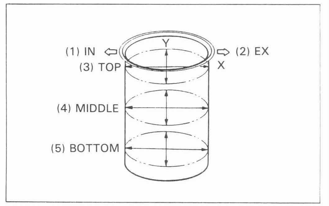
Calculate the cylinder for out-of-round at three levels in an X and Y axis. Take the maximum reading to determine the out-of-round.
SERVICE LIMIT: 0.06 mm (0.002 in)
The cylinder must be rebored and an oversize piston fitted if the service limits are exceeded.
The following oversize pistons are available:
0.25 mm (0.010 in) and 0.50 mm (0.020 in)
The cylinder must be rebored so that the clearance to an oversize piston is 0.010-0.035 mm (0.0004-0.0014 in).
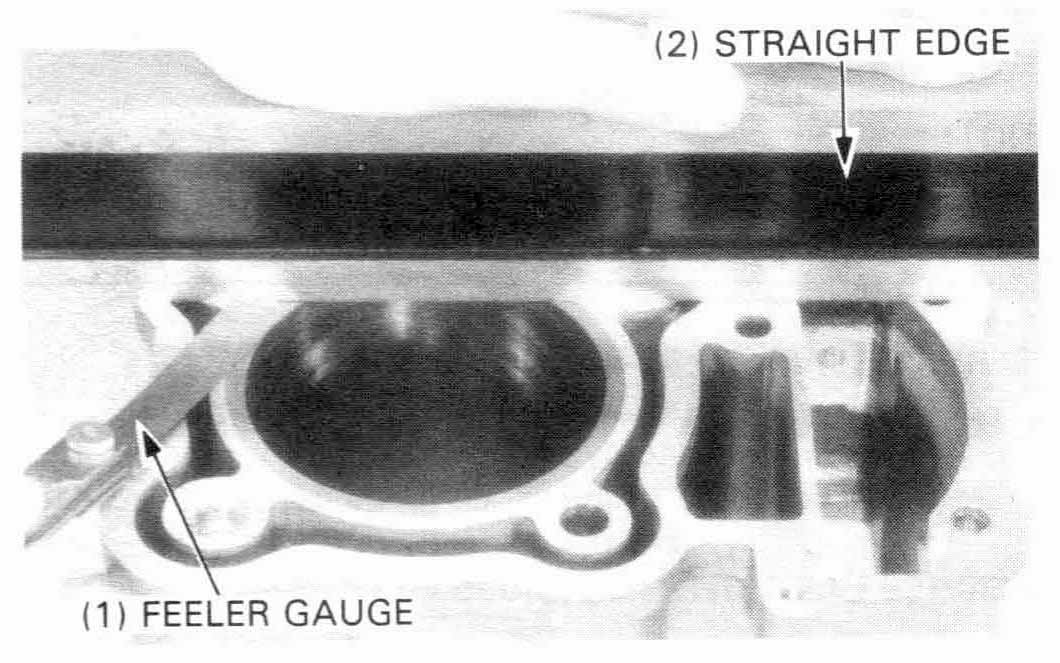
Inspect the cylinders for transverse warpage across the top.
SERVICE LIMIT: 0.10 mm (0.004 in)
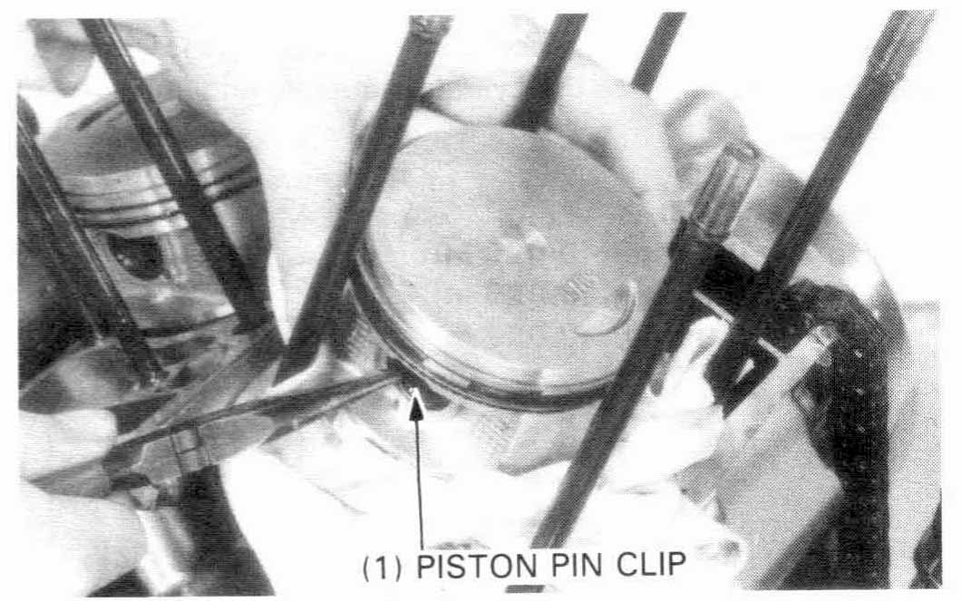
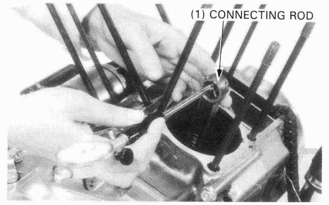
Place a shop towel into the crankcase and remove the piston pin clips.
Clean the piston domes, ring lands and skirts.
Measure the piston ring-to-groove clearance.
| SERVICE LIMITS: | ||
| Top: | 0.11 mm (0.004 in) | |
| Second: | 0.10 mm (0.004 in) | |
If clearance is excessive, replace the piston ring.
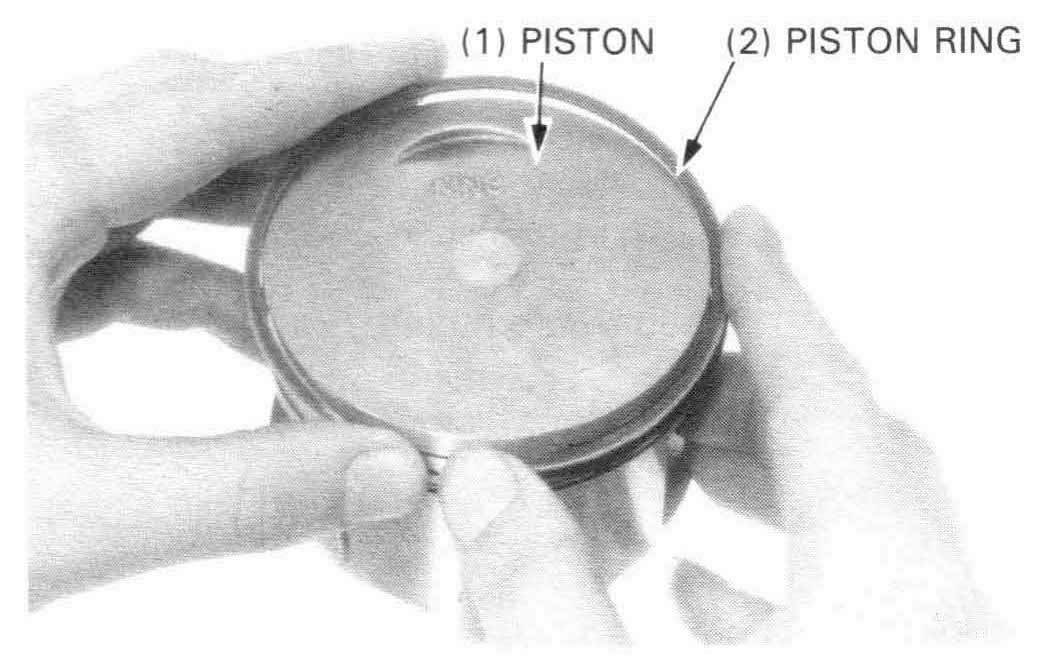
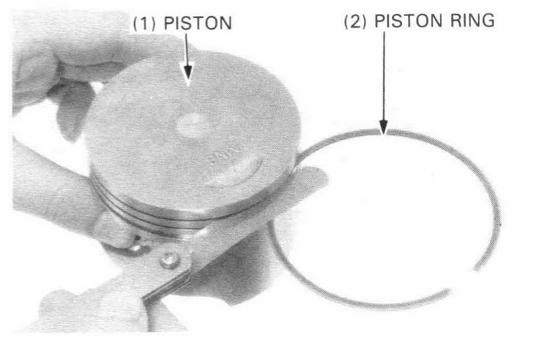
Remove the piston rings and mark them to indicate the correct cylinder and piston position for reassembly.
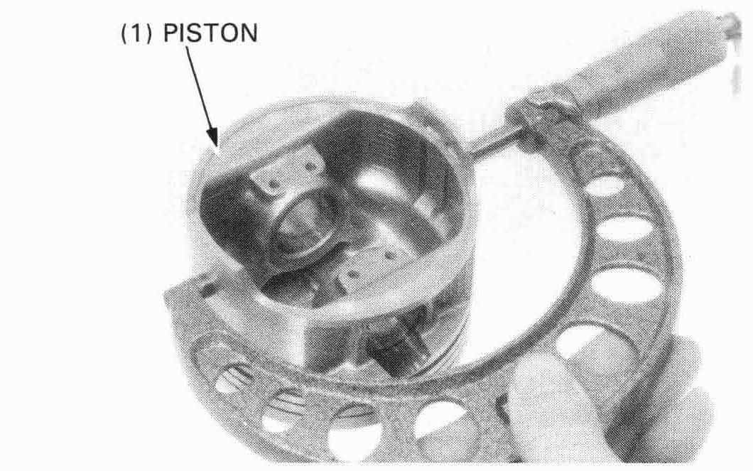
Measure the piston O.D.
| SERVICE LIMIT: 78.92 mm (3.107 in) |
Calculate the piston-to-cylinder clearance by subtracting the piston O.D. from the cylinder I.D. (page 10-2).
| SERVICE LIMIT: 0.13 mm (0.005 in) |
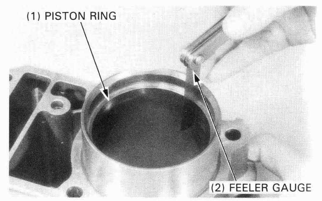
Measure the top and second piston ring end gaps: using a piston, push the ring into the cylinder squarely and make the measurement.
| SERVICE LIMITS: | ||
| Top: | 0.65 mm (0.026 in) | |
| Second: | 0.65 mm (0.026 in) | |
| Oil: | 0.95 mm (0.037 in) | |
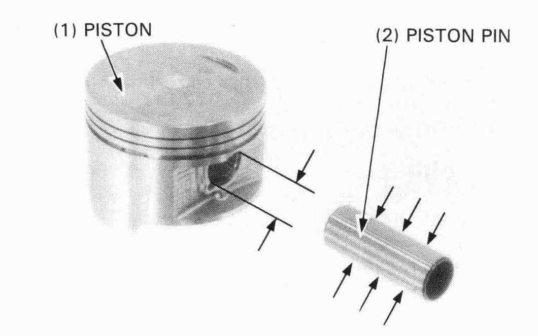
Measure each piston pin bore.
SERVICE LIMIT: 20.018 mm (0.7881 in)
Measure each piston pin O.D.
SERVICE LIMIT: 19.984 mm (0.7867 in)
Calculate the piston pin-to-piston clearance.
SERVICE LIMIT: 0.034 mm (0.0013 in)
Measure the I.D. of the connecting rod small end.
SERVICE LIMIT: 20.04 mm (0.789 in)
Calculate the piston pin-to-connecting rod clearance.
SERVICE LIMIT: 0.060 mm (0.0024 in)
Refer to section 11 for connecting rod replacement.
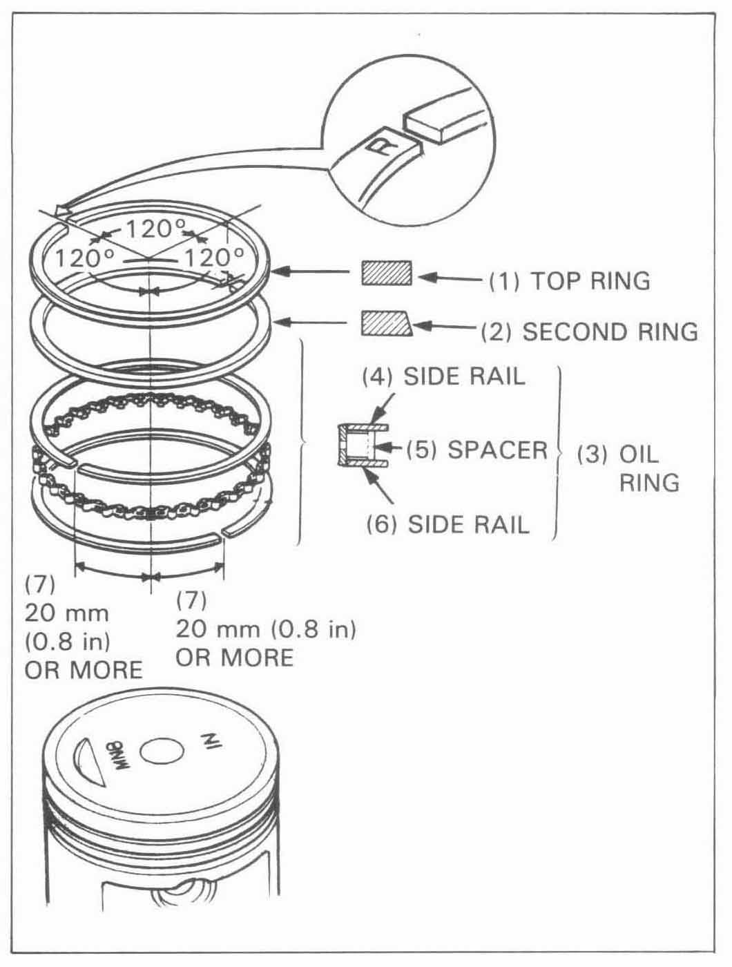
Carefully install the piston rings onto the piston with the markigs facing up.
Stagger the ring end gaps 120° apart from each other as shown.
After installing the rings, check that they rotate freely without sticking.
Place a shop towel into the crankcase.
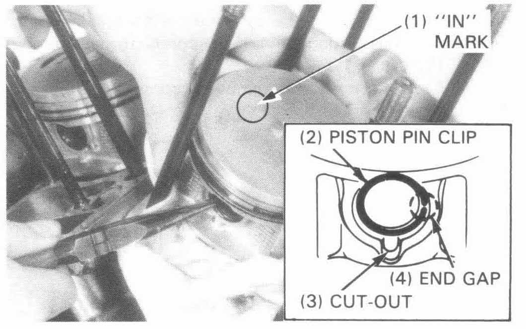
Coat the rod small end with molybdenum disulfide grease. Assemble
the piston and connecting rod with the piston and
Piston pin clips as shown.
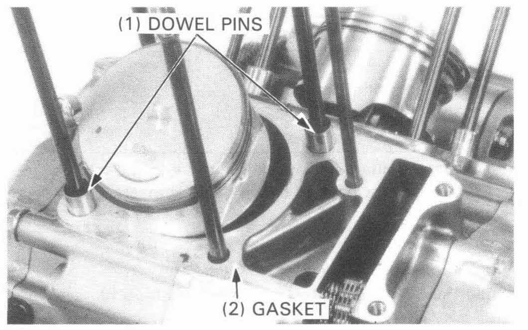
Clean the cylinder gasket surface.
Install the dowel pins and new gasket.
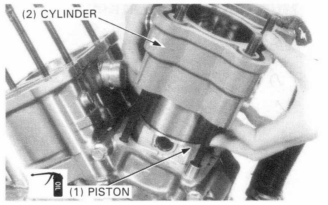
Coat the cylinder, piston ringslgrooves and piston with clean engine oil.
Install the piston assembly into the cylinder from the top of the
crankcase while compressing the piston rings with your fingers.
Be sure each assembly is returned to its original position as
noted during removal.
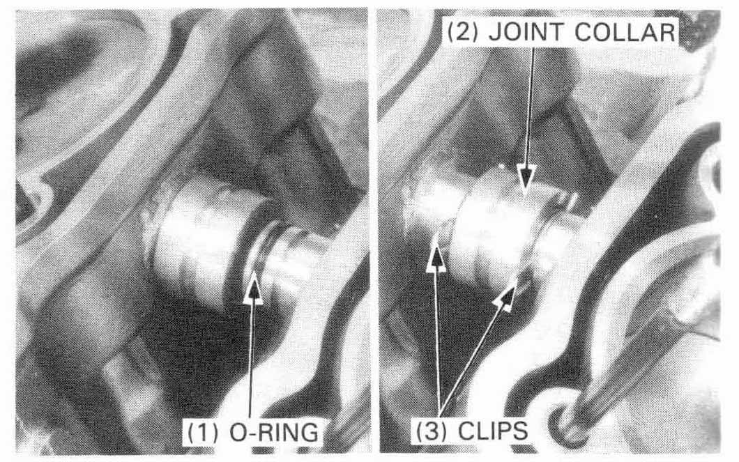
Install a new O-ring onto the cylinder joint and install the cylinder joint collar by sliding the collar toward either cylinder.
Install the clips securely.
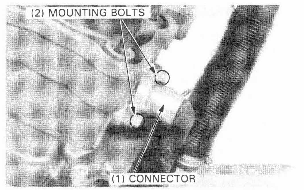
Install a new O-ring into the connector and install and tighten the connector mounting bolts, if the connector was removed.
If only the water hose was removed, connect the hose with the clamp.
Clean the cylinder gasket surface.
Install the cam chain guide.
Install the dowel pins and a new gasket.
Install the cylinder heads and covers (Section 9).