
really big version
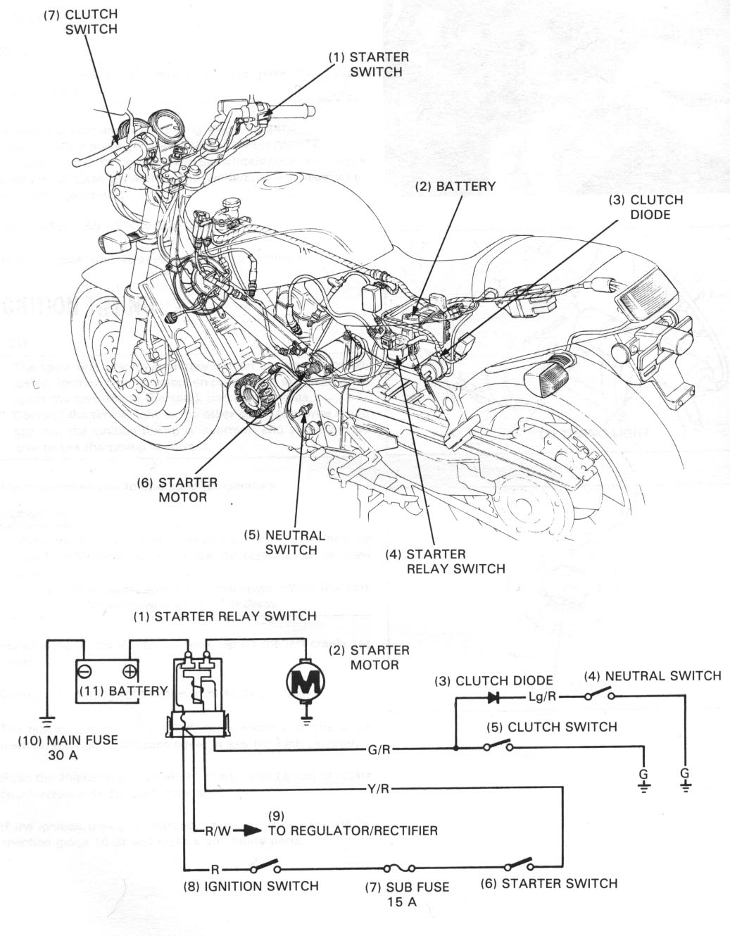
Color wiring diagram with the neutral indicator.
Hawkworks.net main page
Manual main index
| SERVICE INFORMATION | 17-1 |
| TROUBLESHOOTING | 17-1 |
| STARTER MOTOR | 17-3 |
| STARTER RELAY SWITCH | 17-6 |
| CLUTCH DIODE | 17-7 |
Unit: mm (in)
| ITEM | STANDARD | SERVICE LIMIT |
|---|---|---|
| Starter motor brush length | 12.5 (0.49) | 6.5 (0.26) |
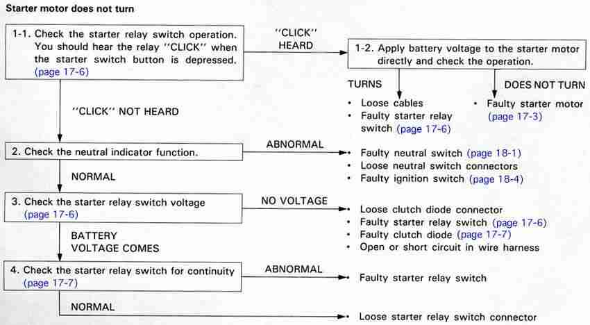
Starter motor turns slowly
Starter motor turns, but engine does not turn
Starter motor and engine turns, but engine does not start
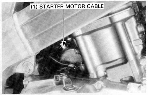
Remove the rubber cap and disconnect thte starter motor cable.
Remove the motor mounting bolts.
Remove the motor from the lefts side.
Remove the following components:
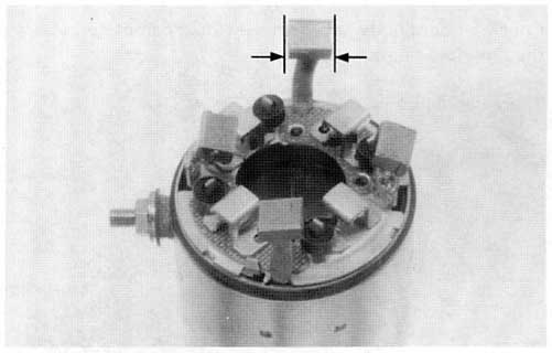
Measure each brush length.
SERVICE LIMIT: 6.5 mm (0.26 in)
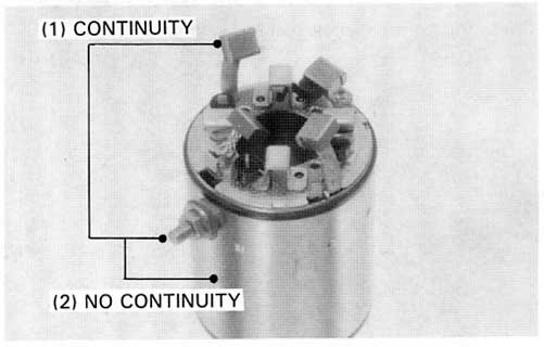
Check for continuity from the cable terminal to the motor case and from the cable terminal to the brush wire (black).
CABLE TERMINAL-MOTOR CASE
NO CONTINUITY: NORMAL
CABLE TERMINAL-BRUSH (BLACK WIRE)
CONTINUITY: NORMAL
Disassemble the brush holder if necessary.
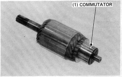
Inspect the commutator bars for discoloration.
Bars discolored in pairs indicate grounded armature coils.
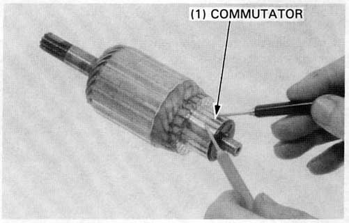
Check for continuity between pairs of commutator bars.
There should be continuity.
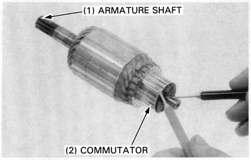
Check for continuity between individual commutator bars and the armature shaft.
There should be no continuity.
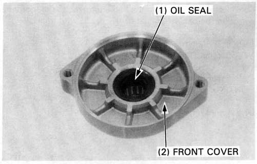
Check the front cover oil seal or wear or fatigue.
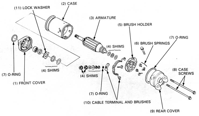
Set the brushes on the brush holder.
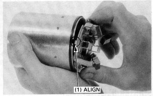
Align the starter motor case notch with the brush holder tab.
Install the armature in the case.
Set the brush springs.
Install the rear shims in the same location and number as
before disassembly.
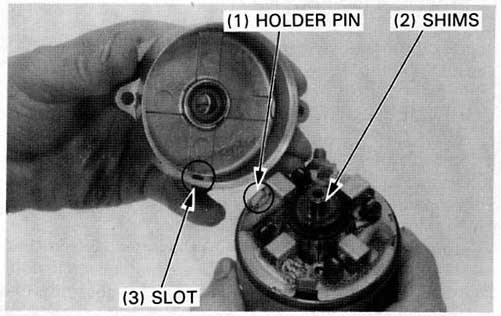
Install the O-ring on the case.
Install the rear cover, aligning its slot with the brush holder pin.
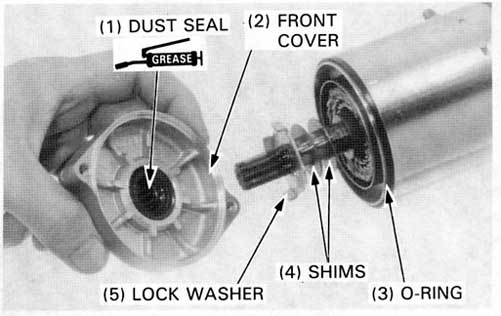
Install the front shims in the same location and number as before desassembly.
Install the O-ring on the case.
Install the lock washer, aligning its tabs with the slots of the front cover.
Apply grease to the dust seal and install the front cover.
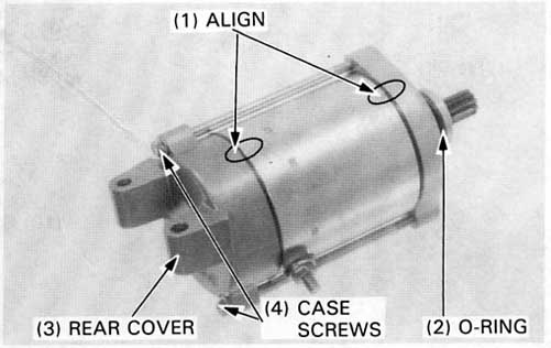
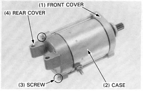
Align index marks of the front cover, case and rear cover as shown.
Install and tighten the starter motor case screws and apply oil to the O-ring and install it on the front cover.
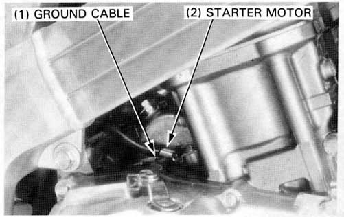
Install the starter motor in the engine.
Install and tighten the motor mounting bolts securely.
Connect the motor cable to the motor terminal and install the rubber cap over the terminal.
Connect the battery negative cable.
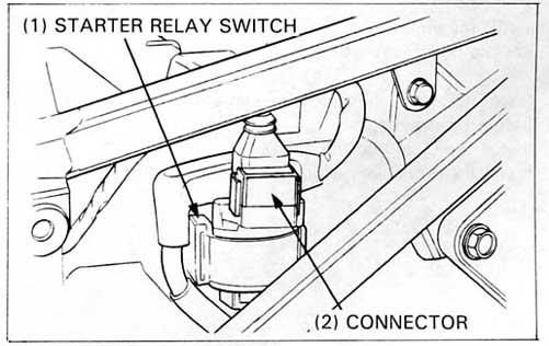
Depress the starter switch button with the ignition switch ON.
The coil is normal if the starter relay switch clicks.
If you don’t hear the switch “CLICK”, disconnect the
switch connector.
Shift the transmission into neutral and turn the ignition switch ON.
Measure the voltage between the Yellow/Red (+) and Green/RED (–) wires
of the relay connector as you press the starter. The tester
should show battery voltage. If it does not, make the following
continuity inspection.
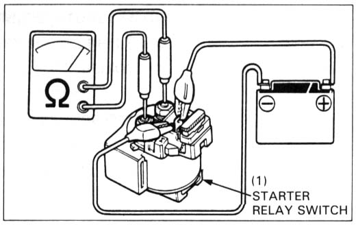
Remove the starter relay switch.
Connect an ohmmeter to the switch large terminals.
Connect a fully charged 12 V batter positive wire to the starter relay switch Yellow/Red wire terminal, and the battery negative wire to the Green/Red wire terminal.
There should be continuity while th battery is connected to the terminals, and no continuity when the battery is disconnected.
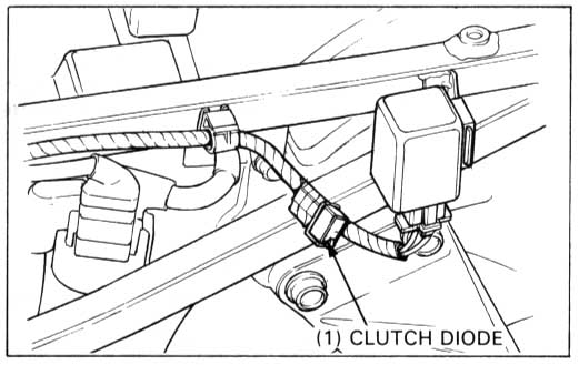
Remove the rear cowling (page 13-25).
Remove the clutch diode from the wire harness.
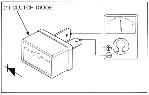
Check for continuity with an ohmmeter.
Connect the positive probe to the (+) terminal and the negative probe to the (-) terminal of the diode.
There should be continuity, then reverse the probes, there should be no continuity.