really big verson
Hawkworks.net main page
Manual main index
| SERVICE INFORMATION | 13-1 |
| TROUBLESHOOTING | 13-2 |
| REAR WHEEL | 13-3 |
| SPROCKET | 13-6 |
| ECCENTRIC BEARING CARRIER REMOVAL | 13-6 |
| BEARING REPLACEMENT | 13-9 |
| SPINDLE | 13-11 |
| ECCENTRIC BEARING CARRIER INSTALLATION | 13-12 |
| SHOCK ABOSORBER | 13-14 |
| SWINGARM | 13-19 |
| MUFFLER/EXHAUST PIPE | 13-24 |
| SEAT | 13-25 |
| REAR COWLING | 13-25 |
Unit: mm (in)
| ITEM | STANDARD | SERVICE LIMIT | |
|---|---|---|---|
| Rear wheel rim runout | Radial | — | 2.0 (0.08) |
| Axial | — | 2.0 (0.08) | |
| Shock absorber spring free length | — | 148.3 (5.84) | |
| Shock absorber spring preload adjuster position | 3 | — | |
| Compression force qt 10 mm (0.4 in) compressed | 15-20 kg (33.1-44.1 lb) | 14.9 kg (32.8 lb) | |
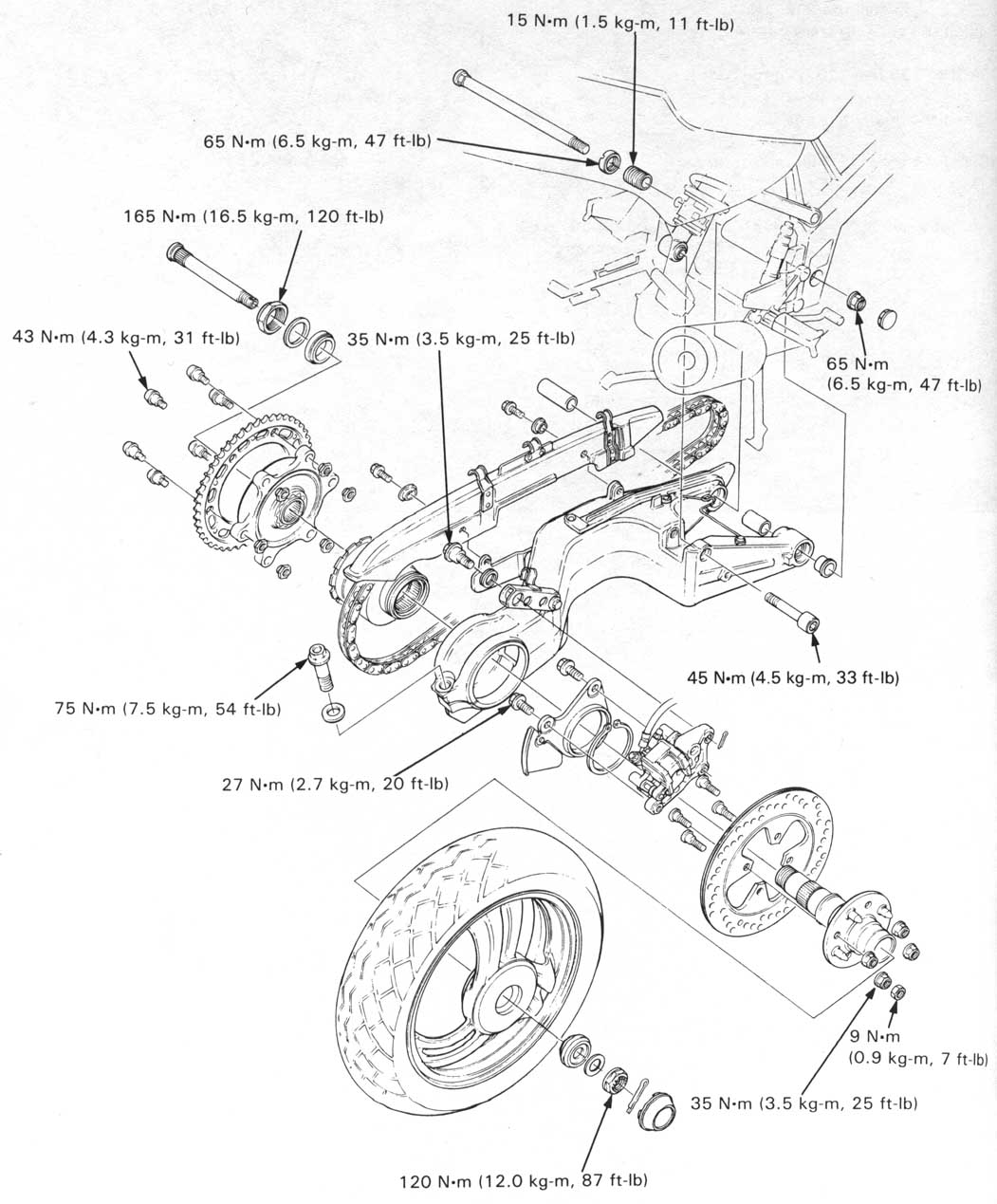
| Sprocket mounting bolt | 43 N•m (4.3 kg-m, 31 ft-lb) |
| Brake disk retaining bolt | 35 N•m (3.5 kg-m, 25 ft-lb) |
| Brake disk retaining bolt lock nut | 9 N•m (0.9 kg-m, 7 ft-lb, 84 in-lb) |
| Rear wheel nut | 120 N•m (12.0 kg-m, 87 ft-lb) |
| Eccentric bearing carrier pinch bolt | 75 N•m (7.5 Kg-m, 54 ft-lb) |
| Shock absorber mounting bolt: upper side | 65 N•m (6.5 kg-m, 47 ft-lb) |
| Shock absorber mounting bolt: lower side | 54 N•m (4.5 kg-m, 33 ft-lb) |
| Damper rod lock nut | 62 N•m (6.2 kg-m, 45 ft-lb) Apply a locking agent to the threads |
| Swingarm pivot nut | 65 N•m (6.5 kg-m, 47 ft-lb) |
| Swingarm pivot lock nut | 65 N•m (6.5 kg-m, 47 ft-lb) |
| Swingarm pivot adjusting bolt | 15 N•m (1.5 kg-m, 11 ft-lb, 132 in-lb) |
| Brake torque rod bolts | 35 N•m (3.5 kg-m, 25 ft-lb) |
| Sub-frame mounting bolts | 40 N•m (4.0 kg-m, 29 ft-lb) |
| Fuel filter base mounting bolt | 22 N•m (2.2 kg-m, 16 ft-lb, 192 in-lb) |
| Eccentric bearing carrier lock nut | 165 N•m (16.5 kg-m, 120 ft-lb) Staked nut |
| Special | |
| Snap ring pliers | 07914—323000 — Equivalent commercially available in the U.S.A. |
| Shock absorber compressor attachement | 07967—KE10000 |
| Driver shaft | 07946—MJ00000 |
| Bearing remover set | 07946—MJ00200 |
| — Driver head | 07946—KA30200 Not available in the U.S.A. |
| Spherical bearing driver | 07908—ME90000 |
| Lock nut wrench | 07965—KE80100 |
| Oil seal driver | 07965—KE80100 |
| Common | |
| Driver | 07749—0010000 |
| Attachment, 24 x 26 mm | 07746—0010700 |
| Attachment, 32 x 35 mm | 07746—0010100 |
| Attachment, 42 x 47 mm | 07746—0010300 |
| Attachment, 52 x 55 mm | 07746—0010400 |
| Attachment, 62 x 68 mm | 07746—0010500 |
| Pilot, 15 mm | 07746—0040300 |
| Pilot, 17 mm | 07746—0040400 |
| Pilot, 20 mm | 07746—0040500 |
| Pilot, 22 mm | 07746—0040000 |
| Pilot, 35 mm | 07746—0040700 |
| Pilot, 40 mm | 07746—0040700 |
| Driver handle | 07949—3710001 |
Place the motorcycle on its center stand.
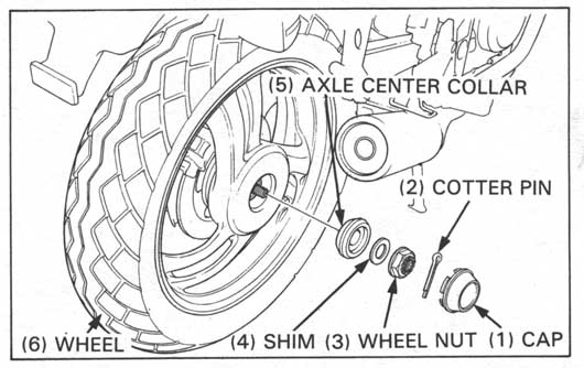
Remove the center cap and cotter pin. Loosen the wheel nut,
but do not remove it.
Info: The rear wheel mounting nut is 27mm.
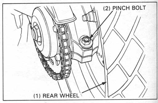
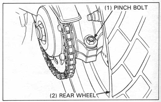
Loosen the eccentric bearing carrier pinch bolt and turn the
carrier counterclockwise until it stops to obtain maximum chain slack.
Remove the chain from the rear sprocket and place it on the
outside of the sprocket.
Rotate the eccentric bearing carrier to its rearward most
(maximum chain slack) position.
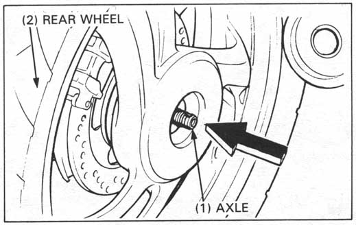
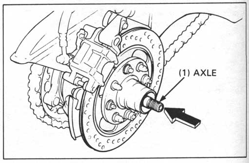
Remove the wheel nut, shim and axle center collar.
Tap the axle with soft hammer and push the axle in until it clears the wheel.
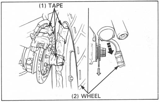
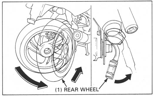
Attach tape to the wheel rim, edge of the spindle and brake caliper to avoid damaging the wheel.
Remove the wheel from the drive pins, then angle it to the right and pull it backward to go between the brake disc and muffler.
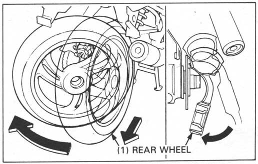
Then, as the wheel reaches the hub, angle it to the left and pull it out backward as shown.
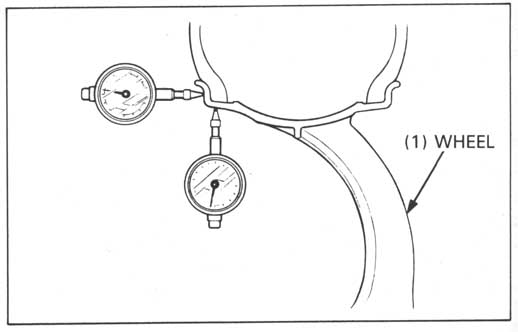
Check the rim runout by placing the wheel in a truing stand.
Spin the wheel slowly and read the runout using a dial indicator.
| SERVICE LIMITS | ||
| RADIAL RUNOUT: | 2.0 mm (0.08 in) | |
| AXIAL RUNOUT: | 2.0 mm (0.08 in) | |
Remove the dust seal from the wheel.
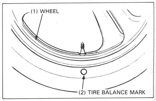
Mount the wheel and tire assembly in an inspection stand.
Spin the wheel, allow it to stop, and mark the lowest (heaviest)
part of the wheel with chalk.
Do this two or three times to verify the heaviest area. If the wheel
is balanced, it will not stop consistently in the same position.
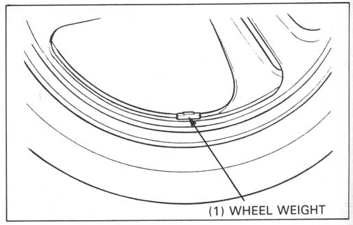
To balance the wheel, install wheel weights on the highest side of
the rim, the side opposite the chalk marks. Add just enough weight so
the wheel will no longer stop in the same position when it’s spun.
Do not add more than 60 grams to the rear wheel.
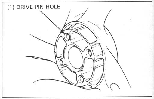
Drive pin hole
Check the drive pin holes for the damage.
Inspection and replacement of the drive pin: turn to page 13-11.
Install the rear wheel in the reverse order of removal.
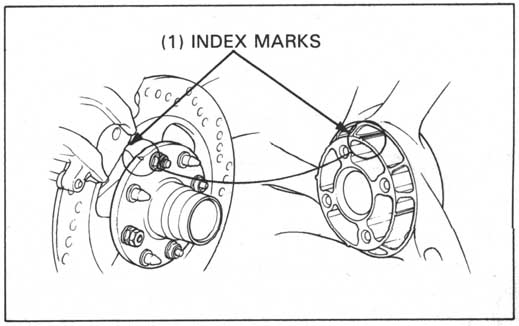
Clean the wheel and spindle mating surface.
Align the index marks and install the wheel hub over the drive
pins.
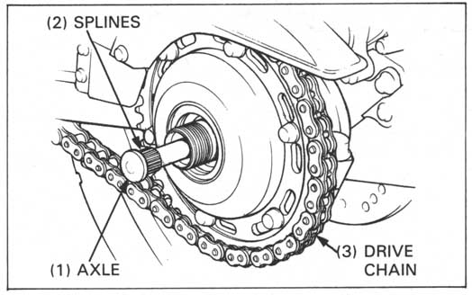
Insert the axle in the wheel hub, making sure the splines are correctly aligned.
Tap the axle with soft hammer to seat the axle securely.
Turn the eccentric bearing carrier counterclockwise until it stops.
Install the drive chain onto the rear sprocket.
Clean and apply clean grease to the axle threads.
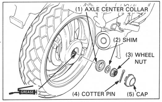
Install the axle center collar, shim and wheel nut.
Tighten the wheel nut to the specified torque.
TORQUE: 120 N•m (12.0 kg-m, 87 ft-lb)
Install a new cotter pin and cap securely.
Apply the rear brake several times and check for free wheel rotation when released.
Adjust the drive chain slack (page 3-12).
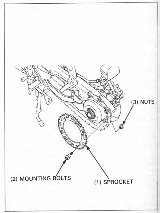
Turn the eccentric bearing carrier to loose the drive chain, then remove the chain from the sprocket.
Remove the sprocket mounting bolts and the sprocket.
Install the sprocket by using the bolts and nuts.
TORQUE: 43 N•m (4.3 kg-m, 31 ft-lb)
Reinstall the drive chain and adjust the slack (page 3-12).
Remove the rear wheel (page 13-3).
Loosen the eccentric bearing carrier pinch bolt and turn
the carrier to loosen the drive chain.
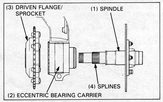
Tap the axle with a soft hammer until the splines clear the driven flange cover.
Remove the axle to the left side.
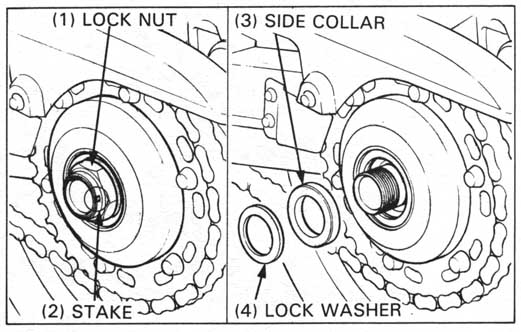
Unstake the eccentric bearing carrier lock nut
and remove the nut.
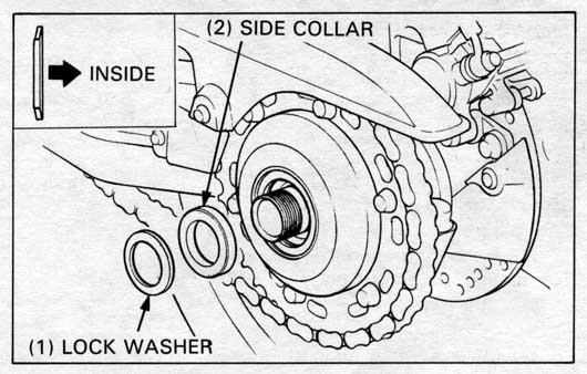
Remove the lock washer and side collar.
Info: The nut is 46mm. A 1-13⁄16" socket is exactly the same size but easier to find and cheaper.
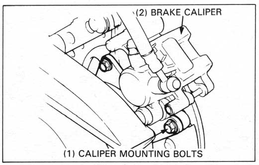
Remove the brake caliper mounting bolts.
Swing the brake caliper from the brake disc while holding it with a
piece of wire or something suitable.
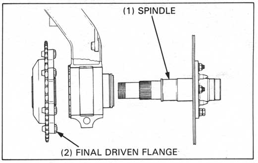
Remove the spindle.
Remove the final driven flange assembly and remove the drive
chain from the sprocket.
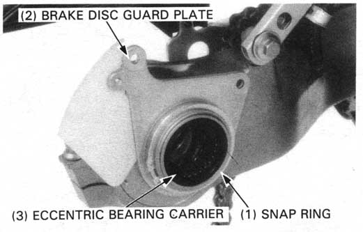
Remove the snap ring and brake disc guard plate.
Remove the eccentric bearing carrier from the swingarm.
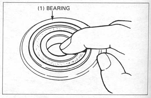
Bearing
Turn the inner races of the ball bearings with your finger.
The bearing should turn smoothly and quietly.
Also check that the bearing outer races fits tightly in
the eccentric bearing carrier.
Check the right bearing needle rollers for obvious signs of wear.
Remove and discard the ball bearings if they do not turn smoothly, quietly, or if they fit loosely in the eccentric bearing carrier (page 13-9).
Replace the needle bearing if it is damaged.
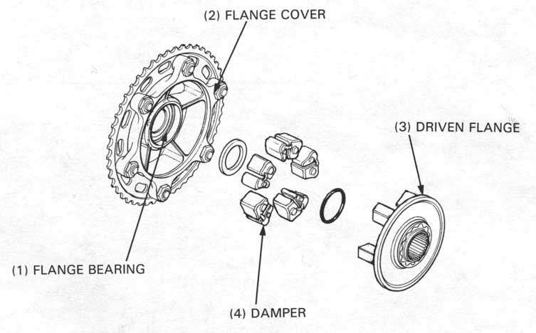
Damper
Separate the driven flange cover with the sprocket from the
flange.
Check the driven flange damper for damage.
Replace the dampers if necessary.
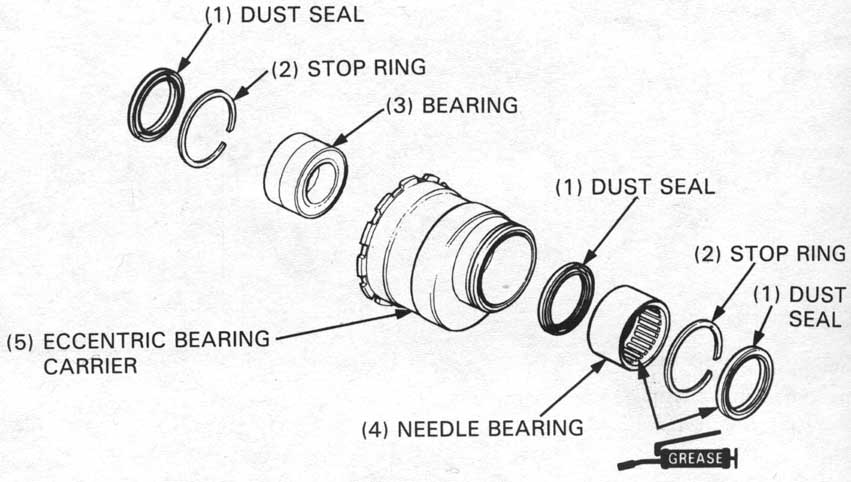
Eccentric bearing carrier
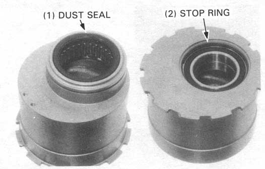
Remove the dust seals and bearing stop rings.
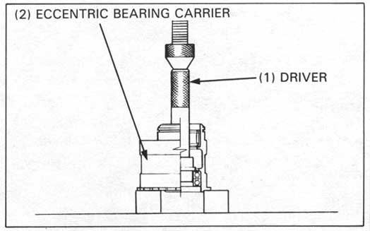
Press the ball bearings out of the carrier first with the special tools.
| TOOLS: | |
| Driver | 07749—0010000 |
| Attachment, 42 x 47 mm | 07746—0010300 |
| Pilot 40 mm | 07746—0040900 |
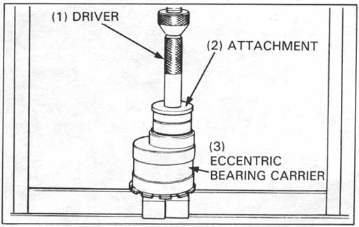
Press the needle bearing out of the carrier with the special tools.
| TOOLS: | |
| Driver | 07749—0010000 |
| Attachment 52 x 55 mm | 07746—0010400 |
Install the inner dust seal in the carrier.
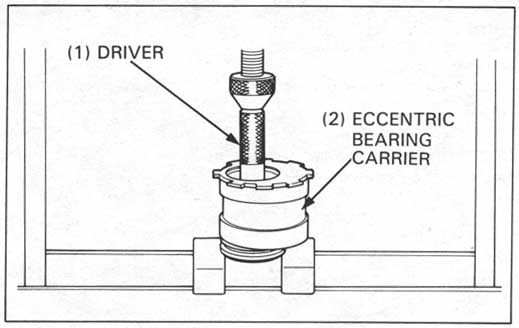
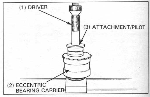
Carefully press the new needle bearing into the carrier
first with the special tools.
| TOOLS: | |
| Driver | 07749—0010000 |
| Attachement 62 x 68 mm | 07746—0010500 |
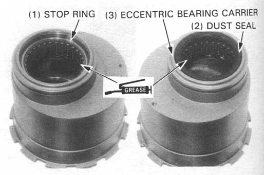
Apply clean grease to the dust seal lip.
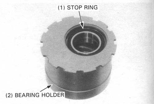
Install the bearing stop ring and dust seal securely.
Carefully press the new ball bearings in with the special tools.
| TOOLS: | |
| Driver | 07749—0010000 |
| Attachment 62 x 68 mm | 07746—0010500 |
Apply clean grease to the dust seal lip.
Install the bearing stop ring and dust seal securely.
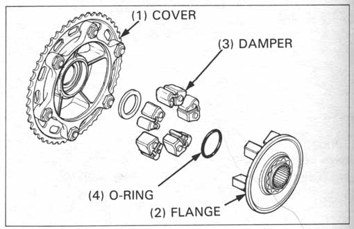
Driven flange
Separate the cover and the flange.
Remove the dampers and the O-ring.
Press the bearing and dust seal out of the cover with the special tools.
| TOOLS: | |
| Driver | 07749—0010000 |
| Attachment 52 x 55 mm | 07746—0010400 |
| Pilot 35 mm | 07746—0040800 |
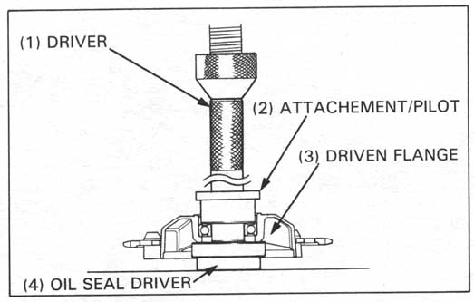
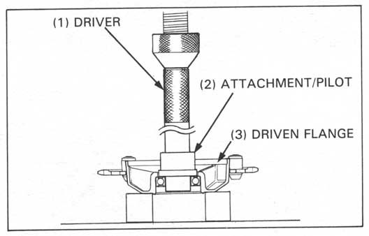
Carefully press the new bearing in with the special tools.
| TOOLS: | |
| Driver | 07749—0010000 |
| Attachment 62 x 68 mm | 07746—0010500 |
| Pilot 35 mm | 07746—0040800 |
| Oil seal driver | 07965—KE80100 |
Install the dust seal securely.
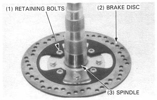
Check the following of the spindle:
If necessary, remove the brake disc retaining bolts and nuts and lock nut, and separate the brake disc from the spindle.
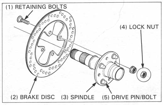
Apply a locking agent to the drive pin bolt threads and tighten the drive pin bolts to the drive pin if replaced them.
TORQUE: 15 N•m (1.5 kg-m, 11 ft-lb)
Install the brake disc to the spindle and tighten the disc retaining bolts and nuts.
TORQUE: 35 N•m (3.5 kg-m, 25 ft-lb)
Install the disc retaining bolt lock nut onto the anywhere bolt.
TORQUE: 9 N•m (0.9 kg-m, 7 ft-lb)
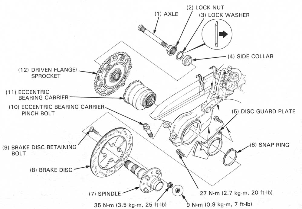
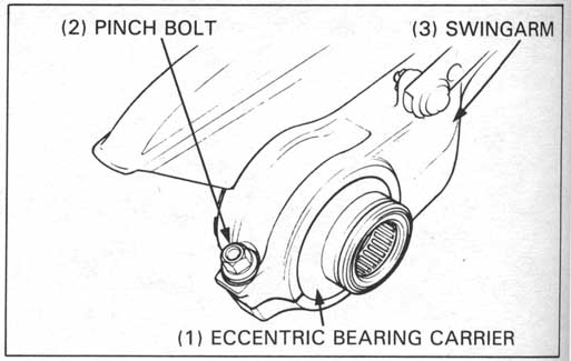
Install the eccentric bearing carrier onto the swingarm.
Loosely install the eccentric bearing carrier pinch bolt.
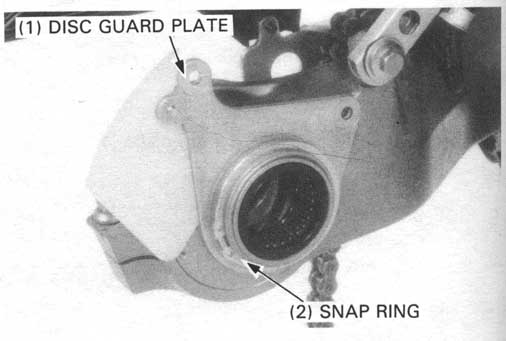
Install the brake disc guard plate onto the eccentric bearing carrier by using the snap ring.
Install the drive chain on the sprocket and position the flange against the eccentric bearing carrier.
Insert the spindle through the bearing carrier and driven flange. Engage the driven flange and the spindle, making sure the splines are correctly mated.
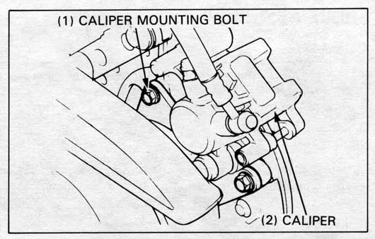
Install over the brake caliper onto the brake disc.
Install and tighten the mounting bolts.
TORQUE: 27 N•m (2.7 kg-m, 20 ft-lb)
Install the rear axle from the left side.
Install the side collar onto the driven flange.
Install the lock washer onto the spindle as shown.
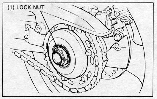
Install the eccentric bearing carrier lock nut and stake it.
TORQUE: 165 N•m (16.5 kg-m, 120 ft-lb)
Install the rear wheel (page 13-5).
Adjust the drive chain slack (page 3-12).
Tighten the eccentric bearing carrier pinch bolt.
TORQUE: 75 N•m (7.5 kg-m, 54 ft-lb)
Operate the brake pedal to seat the caliper piston against the pads.
Raise the rear wheel off the ground by placing the motorcycle on its center stand.
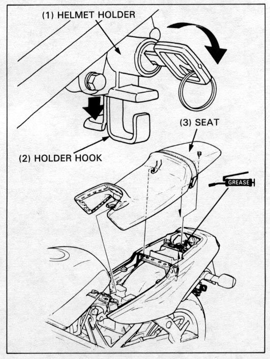
Remove the seat (page 13-25).
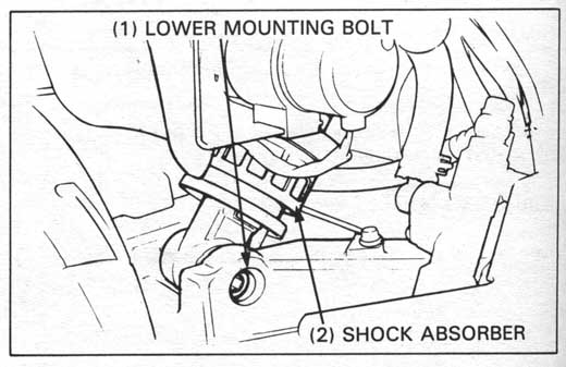
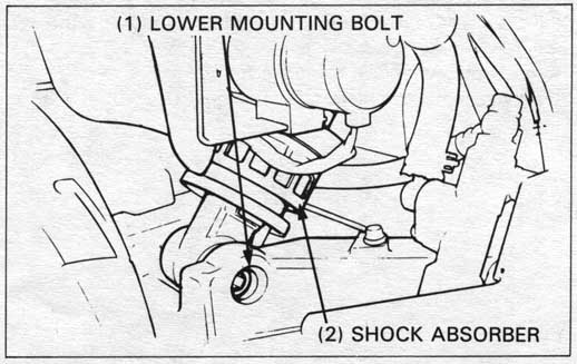
Remove the shock absorber lower mounting bolt while
supporting the wheel.
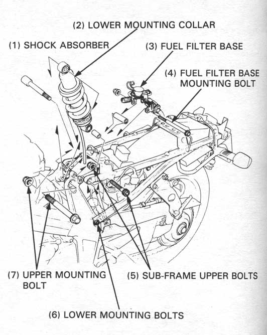
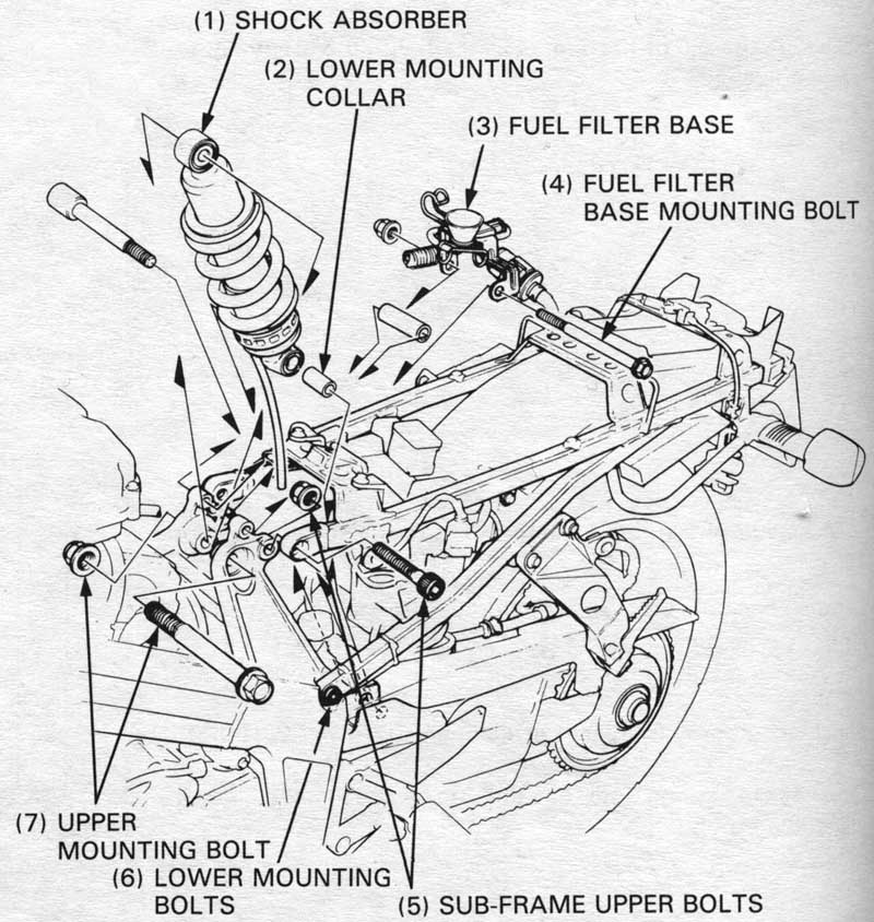
Remove the following:
Loosen the sub-frame lower mounting bolts and lower the subframe.
Pull the shock absorber out from the frame through the upper sub-frame pipes.
Remove the shock absorber lower mounting collar.
Make sure the spring adjuster is set to the softest position
before disassembly.
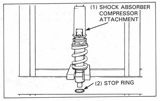
Set the shock absorber in the hydraulic press with the special tool.
| TOOL: | |
| Shock absorber compressor attachement | 07967—KE10000 |
Compress the spring until the stop ring can be removed, and remove the stop ring from the shock absorber.
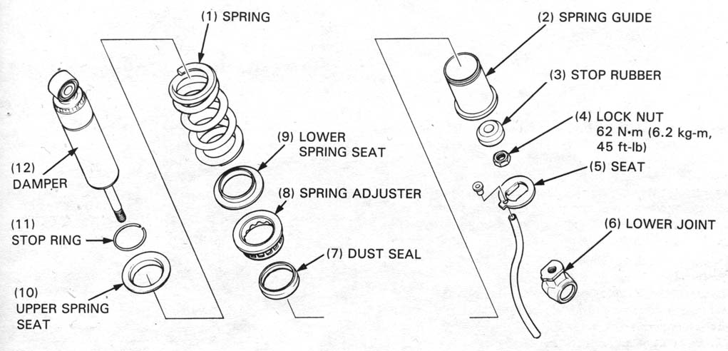
Remove the following:
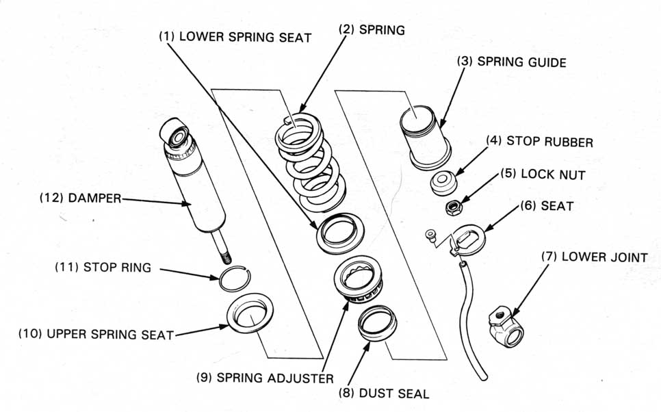
Inspect the following parts:
Inspect all the other parts for wear or damage.
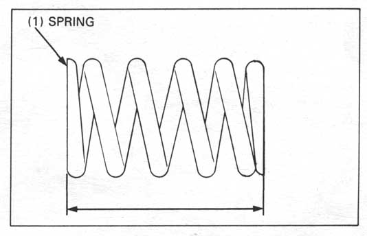
Measure the spring free length.
SERVICE LIMIT: 148.3 mm (5.84 in)
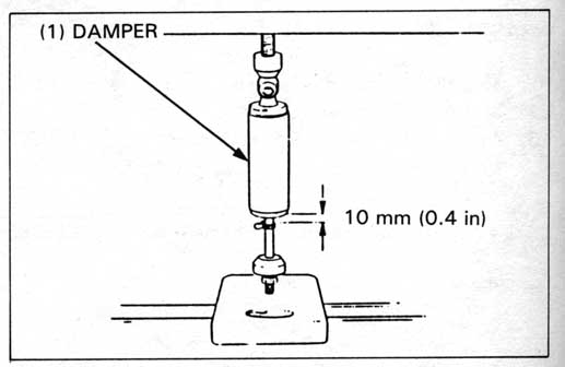
Mark the 10 mm position on the damper rod as shown.
Place the damper rod on a scale and measure the force
required to compress the damper to the 10 mm (0.4 in) mark.
COMPRESSION FORCE: 15 - 20 kg (33.1 - 44.1 lb)
If the force required is less than 14.9 kg (32.8 lb), gas is leaking.
Examine the damper rod and replace the damper unit if it is bent or scored.
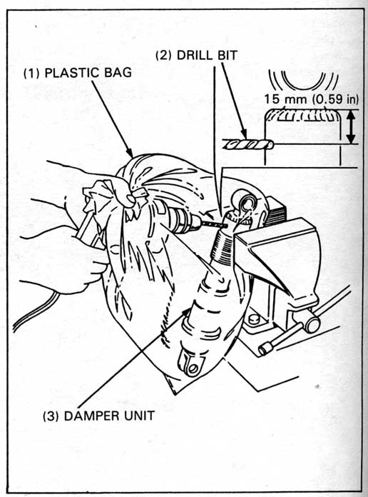
Center punch the damper case to mark the drilling point,
approximately 15 mm (0.59 in) from the top surface.
Wrap the damper unit inside a plastic bag.
Support the damper unit upright in a vise as shown.
Through the open end of the bag, insert a drill motor with
a sharp 2-3 mm (5/64 - 1/8 in) drill bit.
Hold the bag around the drill motor and briefly run the drill motor inside the bag; this will inflate the bag with air from the motor and help keep the bag from getting caught in the bit when you start.
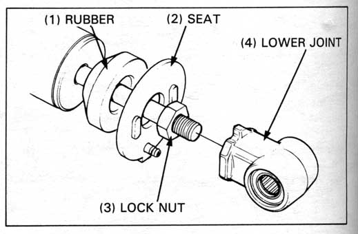
Apply locking agent to the rod threads and install the lock nut.
Screw in the lock nut fully.
Install the seat.
Screw the lower joint onto the damper rod fully, hold it and
tighten the lock nut.
TORQUE: 62 N•m (6.2 kg-m, 45 ft-lb)
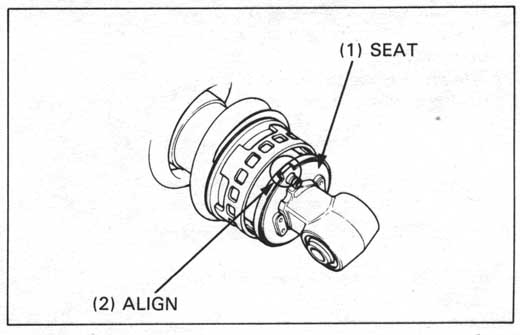
Install the shock absorber drain tube on the seat.
Make sure the tab of the seat is aligned with the groove of the spring guide.
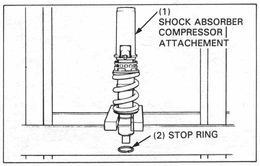
Set the shock absorber in the hydraulic press with the special tool.
| TOOL: | |
| Shock absorber compressor attachment | 07967—KE10000 |
Compress the spring until the stop ring can be installed, and install the stop ring.
Remove the dust seals from the lower mount.
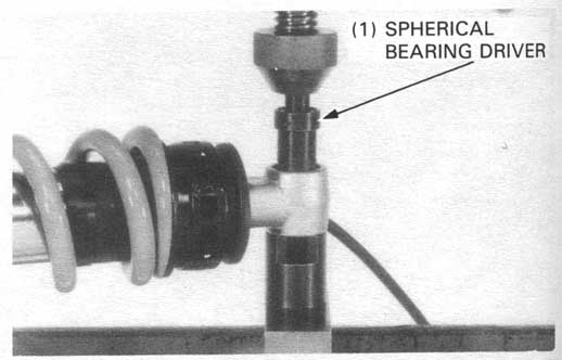
Press the needle bearing out of the shock absorber with the special tool.
| TOOL: | |
| Spherical bearing driver | 07946—KA30200 Not available in U.S.A. |
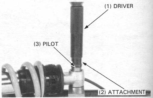
Apply clean grease to a new needle bearing and drive it into the shock absorber until it is flush with lower mount surface.
| TOOLS: | |
| Driver | 07749—0010000 |
| Attachment 24 x 26 mm | 07746—0010700 |
| Pilot 17 mm | 07746—0040400 |
Apply clean grease to the dust seal lips and install them onto the lower mount.
Install the lower mounting collar into the mount.
Install the shock absorber in the frame with the drain tube
facing forward.
Tighten the shock absorber upper mounting bolt.
TORQUE: 65 N•m (6.5 kg-m, 47 ft-lb)
Install the fuel filter base and mounting bolt.
TORQUE: 22 N•m (2.2 kg-m, 16 ft-lb)
Install the sub-frame upper mounting bolts.
TORQUE: 40 N•m (4.0 kg-m, 29 ft-lb)
Tighten the sub-frame lower mounting bolts.
TORQUE: 40 N•m (4.0 kg-m, 29 ft-lb)
Route and clamp the shock absorber drain tube.
Install the shock absorber lower mounting bolt.
TORQUE: 45 N•m (4.5 kg-m, 33 ft-lb)
Raise the rear wheel off the ground by placing the motorcycle
on its center stand.
Remove the rear wheel (page 13-3)
and eccentric bearing carrier (page 13-6).
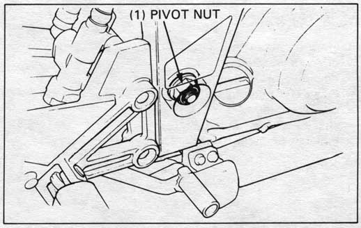
Remove the shock absorber lower mounting bolt.
Remove the swingarm pivot nut.
Unhook the rear brake hose and remove the rear brake caliper (page 14-15).
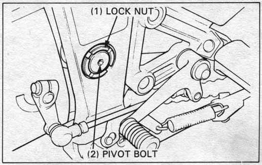
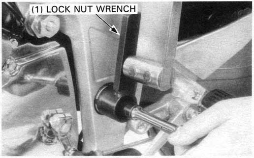
Loosen the lock nut and remove it.
Do not pull the swingarm pivot bolt out at this time.
| TOOL: | |
| Lock nut wrench | 07908—ME90000 |
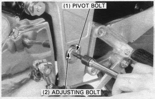
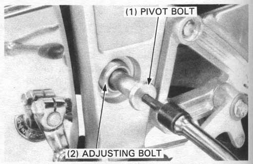
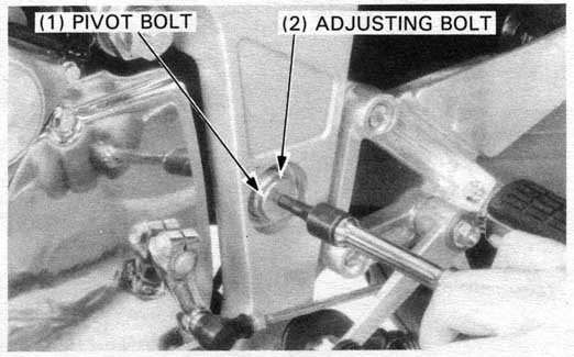
Using a hex wrench, turn the pivot bolt and adjusting bolt counterclockwise together.
Pull the pivot bolt out the frame while supporting the swin-arm.
Remove the swingarm from the frame.
Remove the pivot collars and bushing.
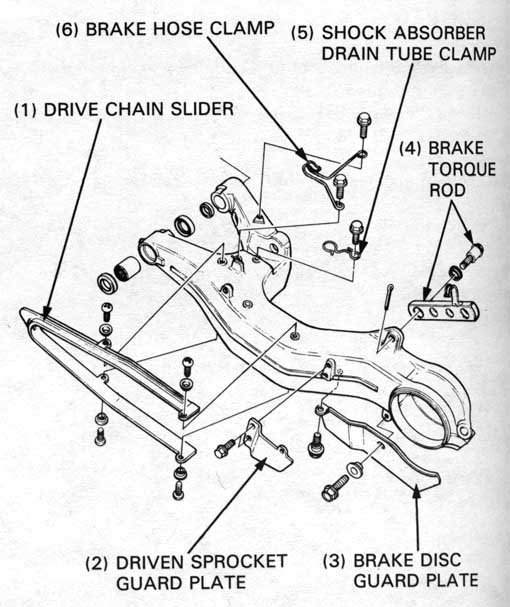
Remove the following components:
Remove the dust seals from the swingarm.
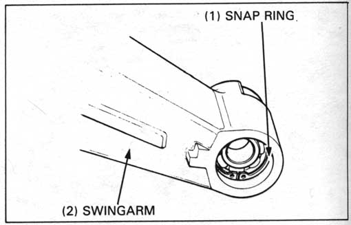
Remove the snap ring from the right side.
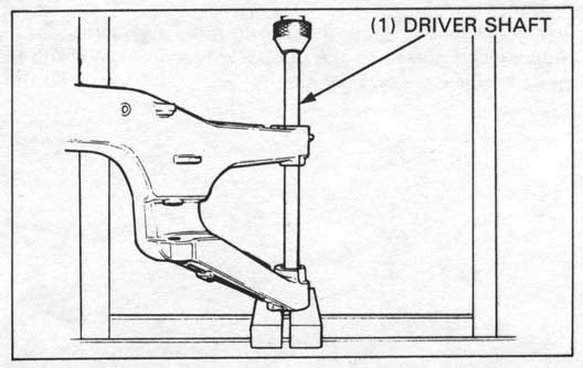
Press the right pivot bearings out of the swingarm using a hydraulic press and the driver shaft.
| TOOL: | |
| Driver shaft | 07746—MJ00100 or |
| Driver handle | 07949—3710001 |
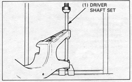
Press the left pivot needle bearing out of the swingarm using a hydraulic press and the special tool.
| TOOL: | |
| Driver shaft set | 07746—MJ00000 |
Apply clean grease to the new pivot bearings.
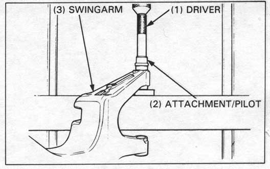
Press the right pivot bearing into the swingarm
until it is flush with the surface.
| TOOLS: | |
| Driver | 07749—0010000 |
| Attachment, 32 x 35 mm | 07746—0010100 |
| Pilot, 15 mm | 07746—0040300 |
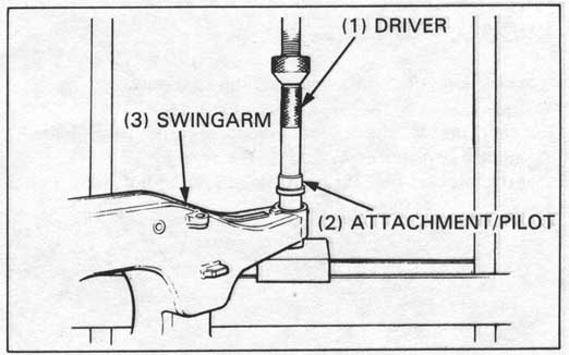
Apply clean grease to the pivot needle bearing.
Press the left needle pivot bearing into the swingarm
until it is flush with the surface.
| TOOLS: | |
| Driver | 07749—0010000 |
| Attachment, 32 x 35 mm | 07746—0010100 |
| Pilot, 22 mm | 07746—0041000 |
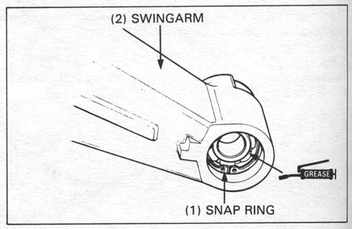
Install the snap ring into the groove in the swingarm.
Apply clean grease to the dust seal lips and install the
dust seals in the swingarm pivots.
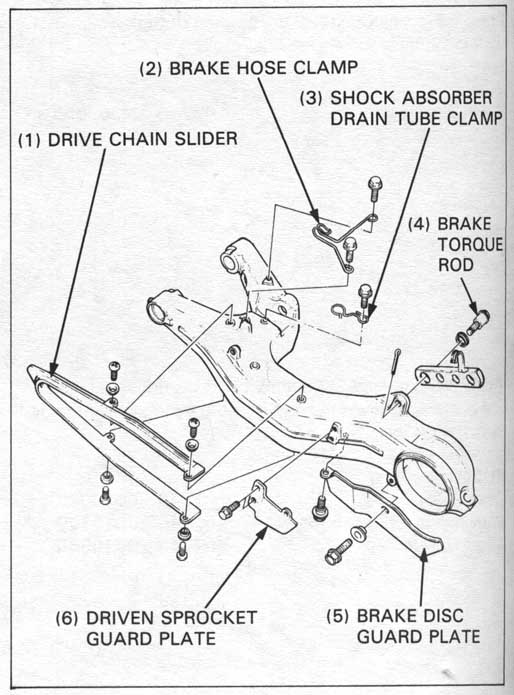
Install the following components:
Install the brake torque rod with a new cotter pin.
TORQUE: 35 N•m (3.5 kg-m, 25 ft-lb)
Install the pivot collars and bushing in the swingarm.
Loosely install the pivot adjusting bolt then install the
swingarm to the frame.
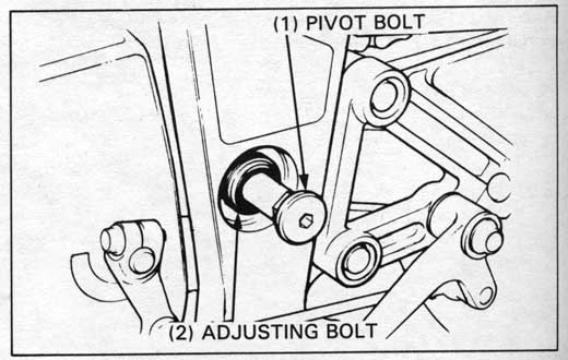
Insert the pivot bolt through the adjusting bolt fully.
Turn the pivot bolt and adjusting bolt together clockwise
until they touch the left pivot collar.
Tighten the adjusting bolt.
TORQUE: 15 N•m (1.5 kg-m, 11 ft-lb)
Loosely install the lock nut.
Tighten the lock nut while holding the adjusting bolt and
pivot bolt.
| TORQUE: | ||
| Actual: | 65 N•m (6.5 kg-m, 47 ft-lb) | |
| Indicated: | 59 N•m (5.9 kg-m, 43 ft-lb) | |
| TOOL: | |
| Lock nut wrench | 07908—ME90000 |
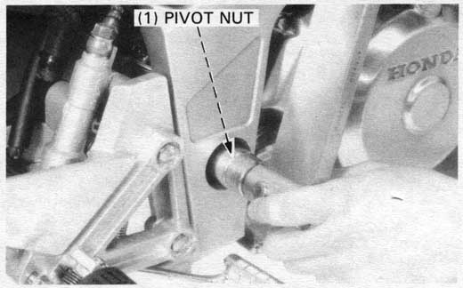
Install the pivot nut and tighten to the specified torque.
TORQUE: 65 N•m (6.5 kg-m, 47 ft-lb)
Install the following:
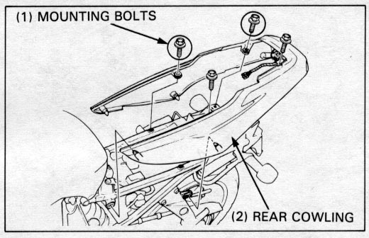
Remove the following:
Loosen the exhaust pipe band bolt and separate the muffler and exjaust pipes.
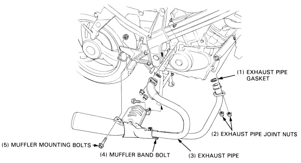
Installation is in the reverse order of removal
Install the exhaust pipe as an assembly.
| TORQUE: | ||
| Exhaust pipe joint nut: | 27 N•m (2.7 kg-m, 20 ft-lb) | |
| Muffler mounting bolt: | 27 N•m (2.7 kg-m, 20 ft-lb) | |
| Muffler band bolt: | 27 N•m (2.7 kg-m, 20 ft-lb) | |