
plenty big verson
Hawkworks.net main page
Manual main index
| SERVICE INFORMATION | 2-1 |
| TROUBLESHOOTING | 2-2 |
| ENGINE OIL LEVEL | 2-3 |
| ENGINE OIL CHANGE | 2-3 |
| OIL FILTER CHANGE | 2-4 |
| OIL PRESSURE CHECK | 2-4 |
| OIL PUMP/RELIEF VALVE | 2-5 |
| CONTROL CABLE LUBRICATION | 2-10 |
| LUBRICATION POINTS | 2-10 |
| Oil Capacity | 2.8 lit (2.94 US qt, 2.46 Imp qt) after disassembly. 2.3 lit (2.43 US qt, 2.02 Imp qt) after disassembly. 2.2 lit (2.32 US qt, 1.94 Imp qt) after draining. |
| Oil recomendation | 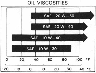 HONDA 4
stroke oil or equivalent API service classification: SE or SF
VISCOSITY: SAE 10W-40 HONDA 4
stroke oil or equivalent API service classification: SE or SF
VISCOSITY: SAE 10W-40Other viscositites shown in the chart may be used when the average temperature in your riding area is within the indicated range. |
| ITEM | STANDARD | SERVICE LIMIT |
|---|---|---|
| Rotor tip clearance | 0.15 mm (0.006 in) | 0.2 mm (0.008 in) |
| Pump body clearance | 0.15-0.22 mm (0.006-0.009 in) | 0.35 mm (0.014 in) |
| Pump end clearance | 0.02-0.07 mm (0.001-0.003 in) | 0.10 mm (0.004 in) |
| Oil pressure | 441 kPa (4.5 kg/cm-sq, 64 psi) at 6,000 rpm (80°C/176°F) | — |
| Oil pressure switch | 12 N•m (1.2 kg-m, 9 ft-lb) Apply sealant to threads |
| Engine oil drain bolt | 35 N•m (3.5 kg-m, 25 ft-lb) |
| Oil filter | 10 N•m (1.0 kg-m, 7.2 ft-lb) |
| Oil filter wrench | 07HAA—PJ70100 |
| Oil pressure gauge | 07506—3000000 or equivalent commercially available in U.S.A. |
| Oil pressure gauge attachment | 07510—4220100 or equivalent commercially available in U.S.A. |
Place the motorcycle on its center stand and shift into neutral.
Start the engine and let it idle for a few minutes.
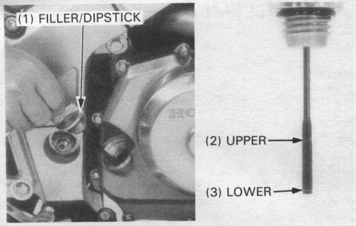
Stop the engine, remove the oil filler cap/dipstick and wipe clean.
Check the oil level with the oil filler cap/dipstick by inserting it without screwing it in.
If the oil level is below the lower level mark on the dipstick, fill
to the upper level mark with the recomended oil.
Check the O-ring for damage.
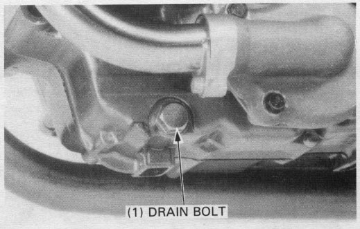
Remove the oil filler cap/dipstick and drain bolt. (17 mm)
With the engine stop switch OFF, start the starter motor for a
few seconds to drain any oil which may be left in the engine.
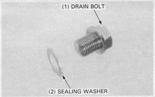
After the oil has drained, check that the drain bolt sealing washer is in good condition, and install the bolt.
Info: The part number for the sealing washer is 94109-14000, and it only costs like $0.25, so get some when you do the next parts order.
TORQUE: 35 N•m (3.5 kg-m, 25 ft-lb)
Fill the crankcase with the correct quantity of the recommended oil.
OIL CAPACITY:
2.8 lit (2.94 US qt, 2.46 Imp qt) after disassembly
2.3 lit (2.43 US qt, 2.02 Imp qt) at oil filter and oil change
2.2 lit (2.32 US qt, 1.94 Imp qt) after draining
| RECOMENDED OIL: | Honda 4-stroke oil or equivalent API service classification: SE or SF VISCOSITY: SAE 10W-40 |
Install the oil filler cap/dipstick.
Start the engine and let it idle for 2-3 minutes.
Stop the engine and wait a few minutes, then check that the oil level is at the upper level mark.
Check that there are no oil leaks.
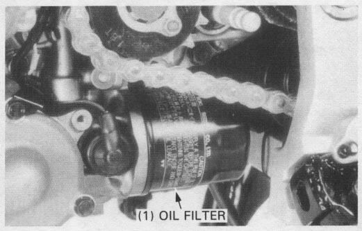
| TOOL: | |
| Oil filter wrench | 07HAA—PJ70100 |
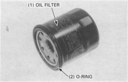
Apply oil to the new oil fiter O-ring and install the new oil filter.
Info: OEM oil filter part number is 15410-MFJ-D01. There are many quality aftermarket filters available; here is an incomplete list.
Tighten the oil filter with a filter wrench.
Torque: 10 N•m (1.0 kg-m, 7.2 ft-lb)
Fill the engine with recomended oil (page 2-3).
Warm the engine up to normal poeration tempererature (approximatesly 80° C/176° F)
Stop the engine.
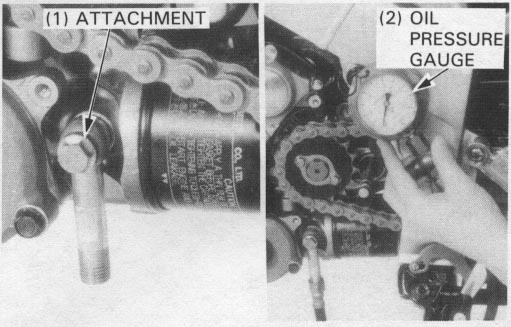
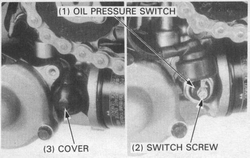
Remove the oil pressure switch and connect an oil pressure gauge attachment and
gauge to the pressure switch hole.
Check the oil level.
| TOOLS: | |
| Oil pressure gauge attachment | 07510—4220100 or equivalent commertially available in U.S.A. |
| Oil pressure gauge | 07506—3000000 or equivalent commertially available in U.S.A. |
Start the engine and check the oil pressure at 6,000 rpm.
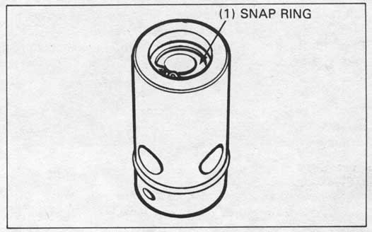
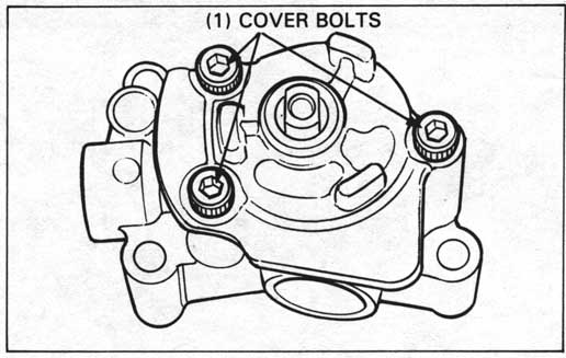
Remove the snap ring and disassemble the relief valve.
| TOOL: | |
| Snap ring pliers | 07914—3230001 |
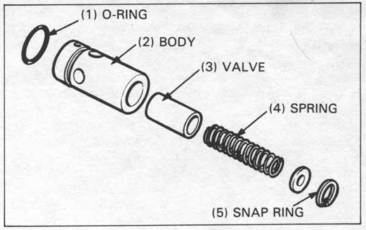
Check the spring, O-ring and valve for fatigue, wear
or damage.
Check the body for clogging or damage.
Clean all the parts and assemble them in the reverse order of disassembly.
Replace the relief valve, if necessary, as an assembly.
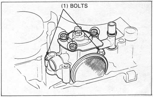
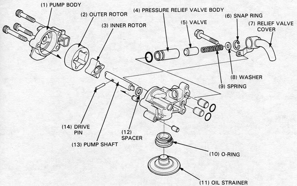
Remove the oil pump by removing two mounting bolts.
Remove the dowel pins and O-rings.
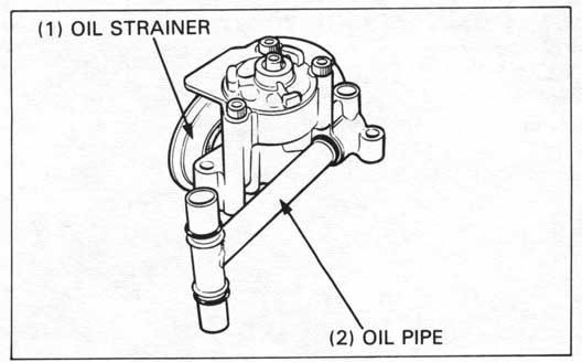
Remove the oil strainer and oil pipe from the oil pump.

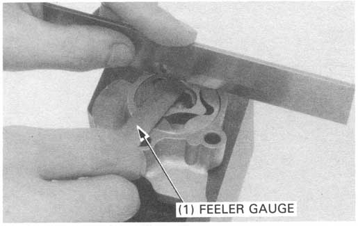
Install the outer and inner rotors to the pump body.
Measure the outer rotor-to-pump body clearance.
SERVICE LIMIT: 0.35 mm (0.014 in)
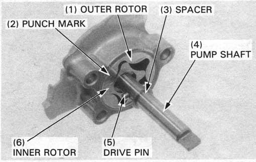
Install the outer rotor in the pump body with the punch mark
facing the cover, then install the inner rotor.
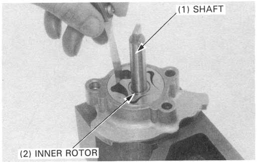
Install the drive pin and spacer on the shaft.
Install the shaft in the body, aligning the drive pin with the inner rotor groove.
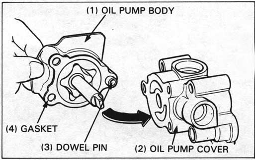
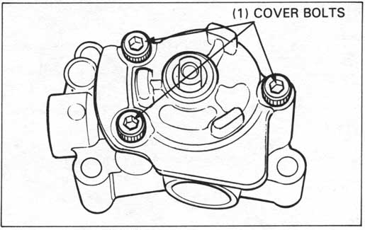
Install the dowel pin and a new gasket on the pump body, then install the cover.
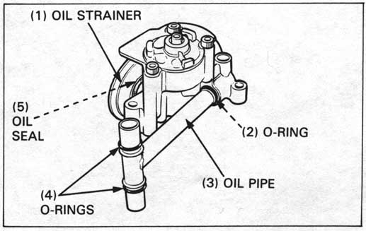
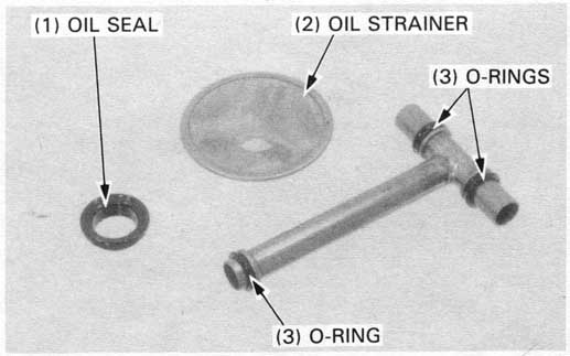
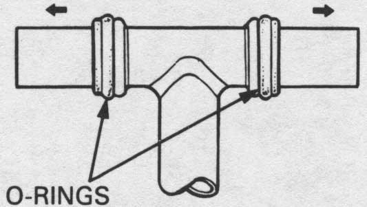
Install the O-rings, oil seal, oil strainer and oil pipe on
the oil pump.
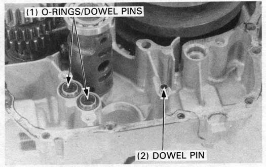
Install the dowel pins and new O-rings.
Install the oil pump as an assembly.
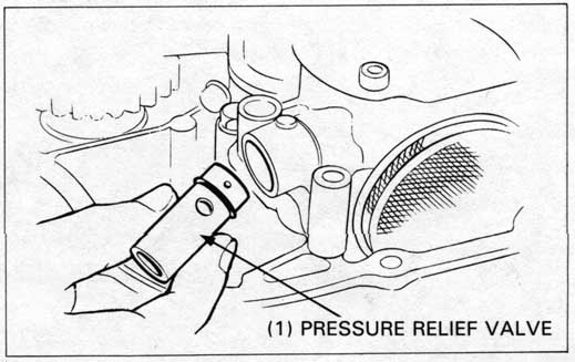
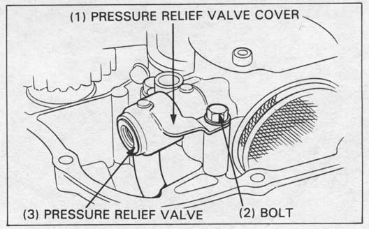
Assemble the pressure relief valve and install it in the oil pump.
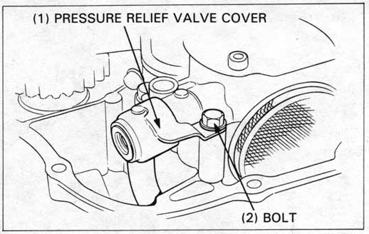
Install the pressure relief valve cover with the bolt. Assemble the crankcase (Section 11).
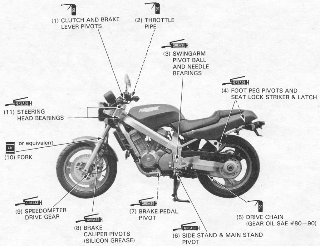
Periodically disconnect the throttle and choke cable at their upper ends. Thoroughly lubricate the cables and their pivot points with a commercially available cable lubricant or a light weight oil.
Use general purpose grease when not otherwise specified here.
Apply oil or grease to the other sliding surfaces and cables
not shown here.