really big verson
Hawkworks.net main page
Manual main index
| SERVICE INFORMATION | 14-1 |
| TROUBLESHOOTING | 14-2 |
| BRAKE FLUID REPLACEMENT/BLEEDING | 14-3 |
| BRAKE PADS/DISKS | 14-5 |
| FRONT MASTER CYLINDER | 14-8 |
| FRONT BRAKE CALIPER | 14-11 |
| REAR BRAKE MASTER CYLINDER | 14-13 |
| REAR BRAKE CALIPER | 14-15 |
| BRAKE PEDAL | 14-17 |
Unit: mm (in)
| ITEM | STANDARD | SERVICE LIMIT | |
|---|---|---|---|
| Brake Disk | Thickness | 5.0 (0.19) | 4.0 (0.16) |
| Warpage | — | 0.3 (0.01) | |
| Master Cylinder I.D. | Front | 12.700-12.743 (0.500-0.5016) | 12.76 (0.502) |
| Rear | 12.700-12.743 (0.500-0.5016) | 12.76 (0.502) | |
| Master piston O.D. | Front | 12.657-12.684 (0.4983-0.4993) | 12.65 (0.498) |
| Rear | 12.657-12.684 (0.4983-0.4993) | 12.65 (0.498) | |
| Caliper cylinder ID | Front | 30.230-30.280 (1.1902-1.1921) | 30.29 (1.193) |
| Rear | 38.180-38.230 (1.5031-1.5051) | 38.24 (1.505) | |
| Caliper piston OD | Front | 30.148-30.198 (1.1870-1.1889) | 30.14 (1.187) |
| Rear | 38.115-38.148 (1.5005-1.5018) | 38.11 (1.500) | |
| Brake Fluid | DOT 4 only | — | |
TORQUE VALUES |
|
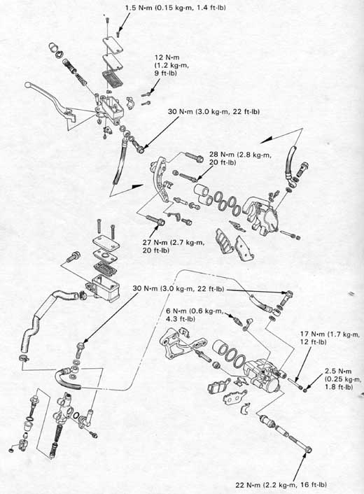
| Front master cylinder holder bolt | 12 N•m (1.2 kg-m, 9 ft-lb) |
| Rear master cylinder mounting bolt | 12 N•m (1.2 kg-m, 9 ft-lb) |
| Brake oil bolt | 30 N•m (3.0 kg-m, 22 ft-lb) |
| Brake reservoir screw | 1.5 N•m (0.15 kg-m, 1.4 ft-lb) |
| Caliper bleed valve | 6 N•m (0.6 kg-m, 4.3 ft-lb) |
| Front caliper mounting bolt | 27 N•m (2.7 kg-m, 20 ft-lb) |
| Front caliper pin bolt | 28 N•m (2.8 kg-m, 20 ft-lb) |
| Rear caliper mounting bolt | 27 N•m (2.7 kg-m, 20 ft-lb) |
| Rear caliper pivot bolt | 22 N•m (2.2 kg-m, 16 ft-lb) |
| Rear caliper pad pin | 17 N•m (1.7 kg-m, 12 ft-lb) |
| Caliper pad pin plug | 2.5 N•m (0.25 kg-m, 1.8 ft-lb) |
| Torque rod bolt | 35 N•m (3.5 kg-m, 25 ft-lb) |
| Front disc retaining bolt | 40 N•m (4.0 kg-m,
29 ft-lb) Apply a locking agent to the threads. |
| Rear disc retaining bolt | 35 N•m (3.5 kg-m, 25 ft-lb) |
| Rear disc retaining bolt lock nut | 9 N•m (0.9 kg-m, 7 ft-lb) |
TOOL |
|
| Special Snap ring pliers |
07914-3230001 |
Brake lever/pedal soft or spongy
Brake lever/pedal too hard
Brake drag
Brakes grab
Brake chatter or squeal
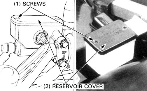
Check the fluid level with the reservoir parallel to the ground.
Remove the reservoir cover, set plate and diaphragm.
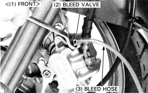
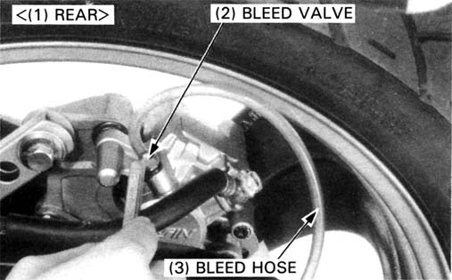
Connect a bleed hose to the bleed valve.
Loosen the caliper bleed valve and pump the brake lever. Stop operating the lever when fluid stops flowing out of the bleed valve.
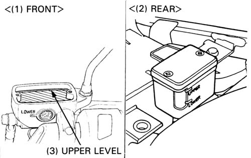
Close the bleed valve; fill the reservoir with DOT 4 brake fluid to the upper level.
Install the diaphragm and reservoir cover.
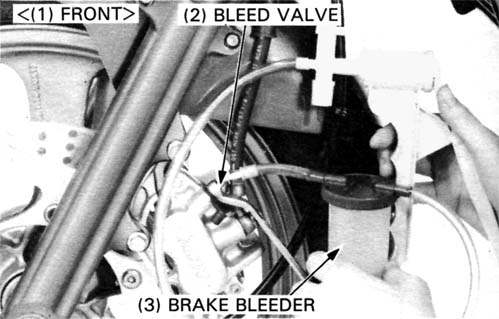
Connect a Brake Bleeder or equivalent to the bleed valve.
Pump the brake bleeder and loosen the bleed valve. Add fluid when the fluid level in the master cylinder reservoir is low. Repeat above procedures until no air bubbles appear in the plastic hose.
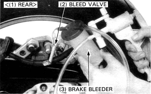
If a brake bleeder is not available, fill the system as follows:
Pump up the system pressure with the lever or pedal until there are no air bubbles in the fluid flowing out of the reservoir hole and lever or pedal resistance is felt.
Bleed the system as follows:
1) Connect a bleed hose to the bleed valve.
2) Squeeze the brake lever (or depress the brake pedal), then open the
bleed valve 1/4 turn and close the valve.
3) Release the brake lever (or pedal) slowly and wait several seconds
after it reaches the end of its travel.
Repeat steps 2 and 3 until bubbles cease to appear in the fluid at the
end of the hose.
Tighten the bleed valve.
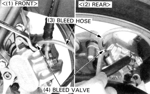
TORQUE: 6 N•m (0.6 kg-m, 4.3 ft-lb)
Close the bleed valve, fill the reservoir with DOT 4 brake fluid to the upper level.
Reinstall the diaphragm and reservoir cover.
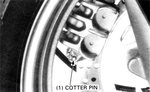
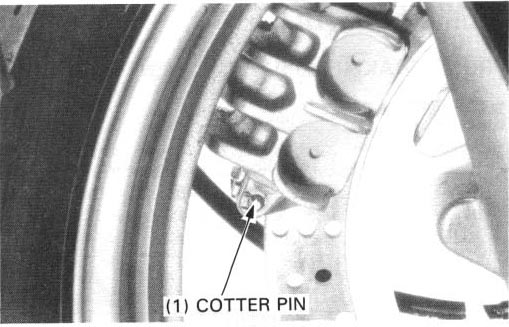
’88 Only:
Remove the cotter pin.
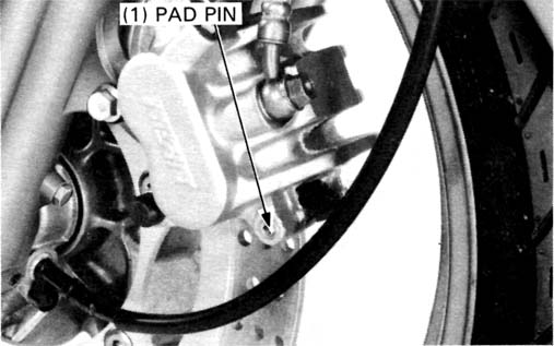
’88 and After ’88:
Remove the pad pin plug and loosen the pad pin.
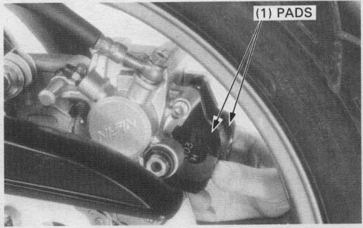
Push the pistons all the way in to allow installation of new brake pads.
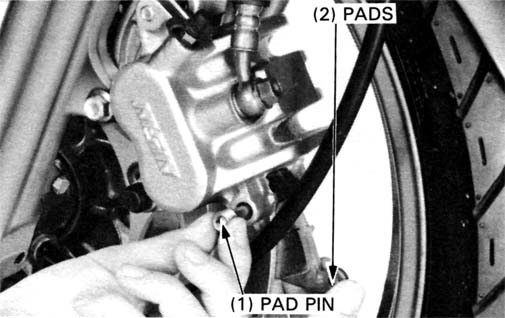
Pull the pad pin out of the caliper and remove the brake pads.
Insert the new brake pads.
Install the pad pin by pushing the pads against the caliper to depress
the pad spring.
TORQUE: 17 N•m (1.7 kg-m, 12 ft-lb)
Install the pad pin plug.
TORQUE: 2.5 N•m (0.25 kg-m, 1.8 ft-lb)
’88 Only:
Install the new cotter pin onto the pad pin.
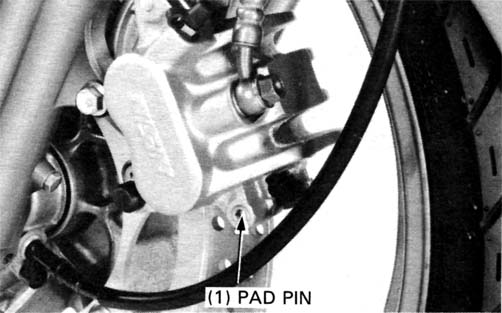
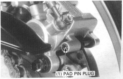
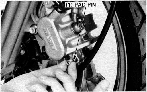
Remove the pad pin plug.
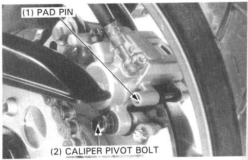
Loosen the pad pin.
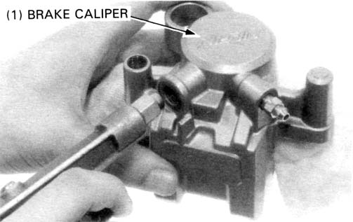
Remove the caliper pivot bolt.
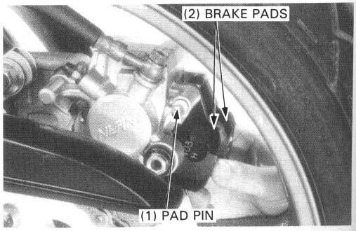
Swing the brake caliper from the brake disc
Pull the pad pin out of the caliper.
Remove the brake pads.
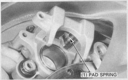
Position the pad spring in the caliper as shown.
Push the piston all the way in to allow installation of new brake pads.
Insert the new brake pads.
Install the pad by pushing the pads against the caliper to depress the pad spring.
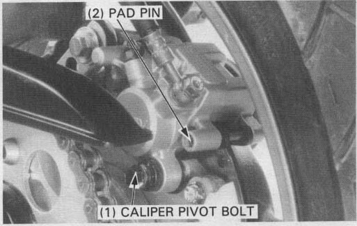
Install the caliper into the brake disc so the disc is positioned between the pads, being careful not to damage the pads.
Install the caliper pivot bolt and tighten it.
TORQUE: 22 N•m (2.2 kg-m, 16 ft-lb)
Tighten the pad pin.
TORQUE: 17 N•m (1.7 kg-m, 12 ft-lb)
Install the pad pin plug.
TORQUE: 2.5 N•m (.25 kg-m, 1.8 ft-lb)
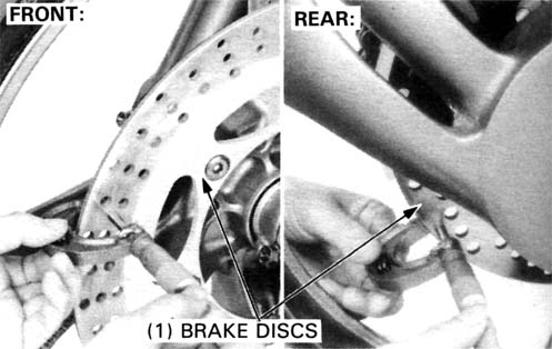
Measure the thickness of each disc.
| SERVICE LIMITS: | Front: 4.0 mm (0.16 in) |
| Rear: 4.0 mm (0.16 in) |
Brake disc removal is referred to:
Front: page 12-18.
<-- ???
Rear: page 13-11.
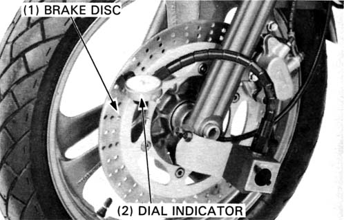
Measure the brake discs for warpage with a dial indicator as shown.
| SERVICE LIMIT: Front/Rear: 0.30 mm (0.012 in) |
Drain brake fluid from the hydraulic system.
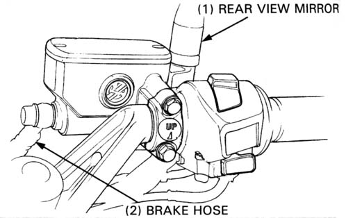
Remove the rear view mirror from the master cylinder and disconnect the
brake light switch wires.
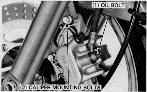
Disconnect the brake hose by removing the oil bolt and sealing washers.
Remove the master cylinder holder bolts and holder, then remove the master cylinder from the handlebar.
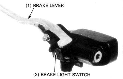
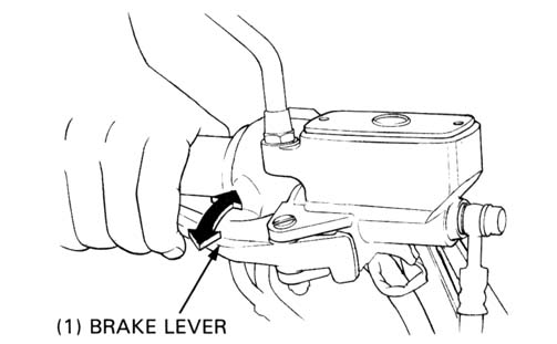
Remove the brake lever and brake light switch.
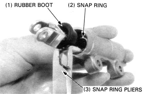
Remove the boot.
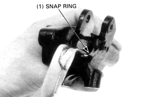
Remove the piston and spring by removing the snap ring.
| TOOL: | |
| Snap ring pliers | 07914—3230001 or equivalent commercially available in U.S.A. |
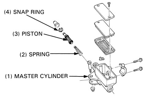
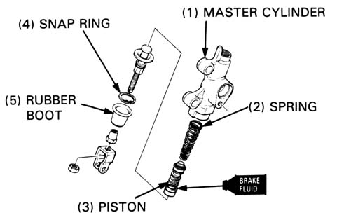
Clean the inside of the master cylinder, reservoir, spring and piston with clean brake fluid.
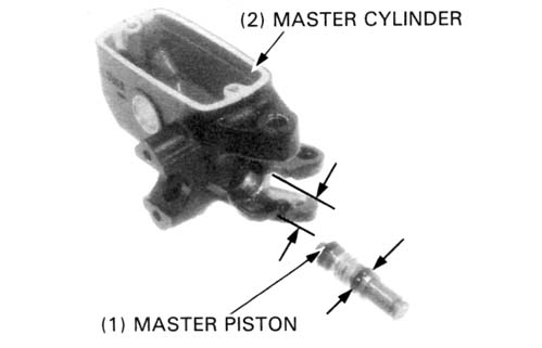
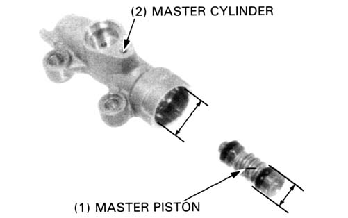
Measure the master cylinder ID
SERVICE LIMIT: 12.76 mm (0.502 in)
Check the master cylinder for scores, scratches or nicks.
Measure the master piston OD at the location shown.
SERVICE LIMIT: 12.65 mm (0.498 in)
Check the primary and secondary cups for damage before assembly.
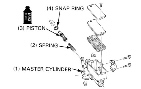
Coat all parts with clean brake fluid before assembly.
Install the spring in the master cylinder with its large diameter facing
inside.
Install the piston.
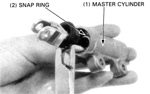
Install the snap ring using a snap ring pliers.
Install the boot.
| TOOL: | |
| Snap ring pliers | 07914—3230001 or equivalent commercially available in U.S.A. |
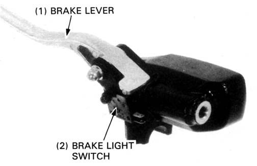
Install the brake lever and brake light switch.
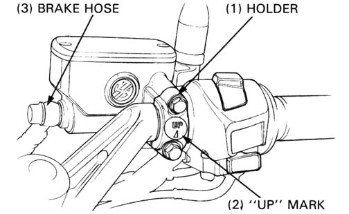
Set the master cylinder onto the handlebar with the holder “UP”
mark facing up.
Temporarily install the holder bolts. Align the slit of the master cylinder
with the punch mark on the handlebar.
Tighten the upper bolt first, then the lower bolt.
Connect the brake light switch wires to the switch terminals.
Install the rear view mirror.
Connect the brake hose with the oil bolt and two sealing washers and tighten
the oil bolt.
TORQUE: 30 N•m (3.0 kg-m, 22 ft-lb)
Fill the reservoir with DOT 4 brake fluid to the casting ledge and bleed the brake system (page 14-4).
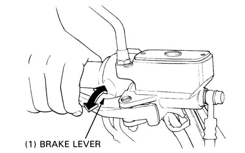
Operate the brake lever to seat the caliper pistons against the pads.
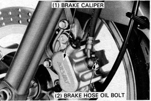
Place a clean container under the caliper and disconnect the brake hose from the caliper by removing the oil bolt and sealing washers.
Remove the brake pads (page 14-5).
Remove the caliper mounting bolts and caliper.
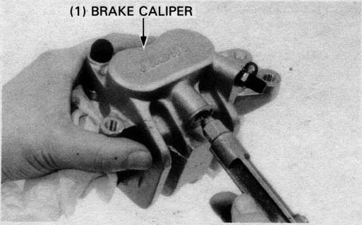
Remove the following:
If necessary, apply compressed air to the caliper fluid inlet to get the pistons out. Place a shop rag under the caliper to cushion the pistons when they are expelled. Use the air in short spurts.
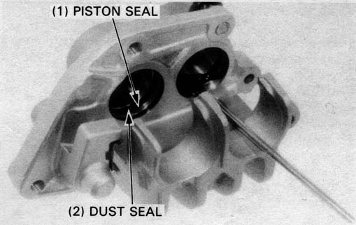
Push the dust seals and piston seals in, lift them out and discard them.
Clean the seal grooves with clean brake fluid.
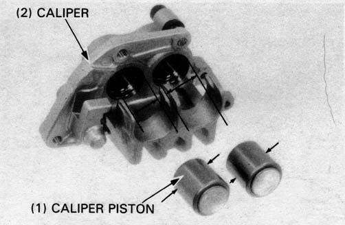
Check the pistons for scoring, scratches or other faults.
Measure the piston OD
SERVICE LIMIT: 30.14 mm (1.187 in)
Check the caliper cylinder for scoring, scratches or other
faults.
Measure the caliper cylinder l.D.
SERVICE LIMIT: 30.29 mm (1.193 in)
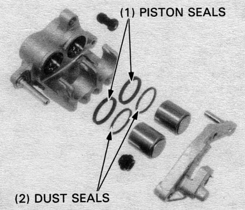
Coat new piston seals and dust seals with clean brake fluid
and install them in the caliper.
Install the pistons with the dished ends toward the pads.
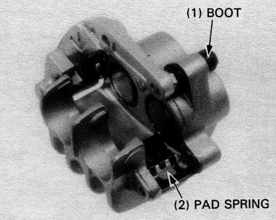
Install the pad spring on the caliper as shown.
Apply silicone grease to the inside of the boot, and install it.
Install the pads and pad pins in the caliper.
Install the caliper assembly over the brake disc so that the disc is positioned between the pads.
Install and tighten the caliper mounting bolts.
TORQUE: 27 N•m (2.7 kg-m, 20 ft-lb, 240 in-lb)
Tighten the pad pins and install and tighten the pad pin plug (page 14-5).
Connect the brake hose to the caliper with the oil bolt and two new sealing washers.
TORQUE: 30 N•m (3.0 kg-m, 22 ft-lb, 264 in-lb)
Bleed the air from the brake system (page 14-4).
Drain the rear brake hydraulic system (page 14-3).
Remove the brake oil bolt and disconnect the brake hose.
Remove the following:
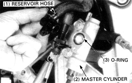
Remove the connector screw and disconnect the reservoir hose from the master cylinder.
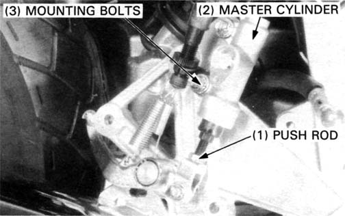
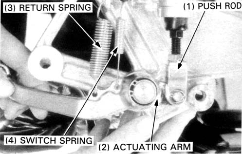
Remove the cotter pin and joint pin, and disconnect the brake actuating arm from the master cylinder push rod. Remove the rear master cylinder from the foot peg bracket.
Remove the rubber boot.
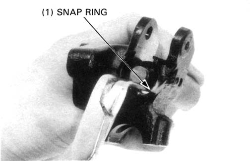
Remove the snap ring and push rod from the master cylinder body.
| TOOL: | |
| Snap ring pliers | 07914—3230001 or equivalent commercially available in U.S.A. |
Remove the master piston and spring.
It may be necessary to apply a small amount of air pressure to the fluid outlet to remove the master piston and spring.
Check the inside of the master cylinder for scores, scratches or nicks.
Measure the inside diameter of the master cylinder bore.
SERVICE LIMIT: 12.76 mm (0.502 In)
Check the piston and piston cups for damage, wear or deterioration.
Measure the master piston OD
SERVICE LIMIT: 12.65 mm (0.498 in)
Clean the master cylinder with compressed air.
Dip the piston cups in clean brake fluid before assembly.
Install the spring and master piston together.
Install the push rod into the master cylinder.
Install the washer, snap ring and rubber boot.
| TOOL: | |
| Snap ring pliers | 07914—3230001 or equivalent commercially available in U.S.A. |
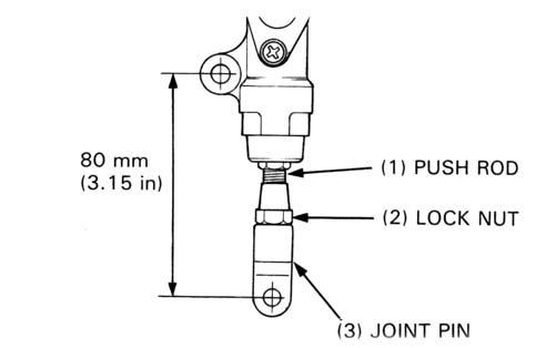
Adjust the push rod standard length so that the distance from the center
of the master cylinder lower mount hole to the center of the joint pin
hole is 80 mm (3.15 in).
Tighten the lock nut
Connect the rear brake actuating arm to the master cylinder push rod with the joint pin, and secure the joint pin with the washer and new cotter pin.
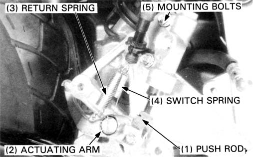
Hook the rear brake pedal return spring and brake light switch spring
to the actuating arm.
Install the brake light switch, switch stay and rear brake master cylinder.
Tighten the master cylinder mounting bolts securely.
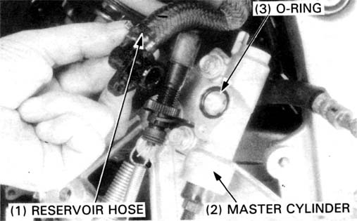
Connect the reservoir hose to the master cylinder with the new O-ring and screw.
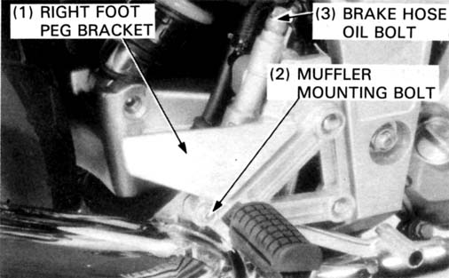
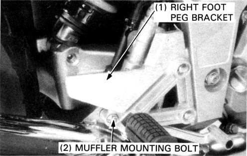
Install the right foot peg bracket. Tighten the mounting bolts.
TORQUE: 22 N•m (2.2 kg-m, 16 ft-lb)
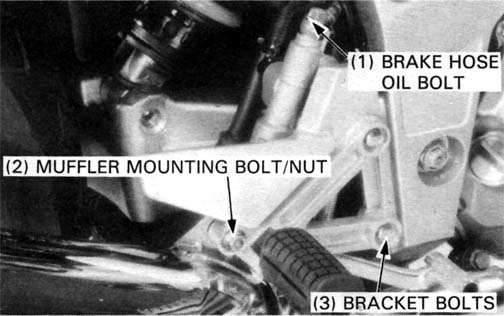
Install the muffler mounting bolt and nut.
TORQUE: 27 N•m (2.7 kg-m, 20 ft-lb)
Connect the rear brake hose with the oil bolt and two new sealing washers.
TORQUE: 30 N•m (3.0 kg-m, 22 ft-lb)
Fill and bleed the rear brake system (page 14-3).
Check the brake light switch operation.
Operate the brake pedal to seat the caliper piston against the pads.
Drain the brake fluid from the hydraulic system.
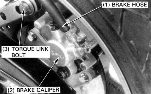
Disconnect the brake hose from the caliper.
Remove the brake pads (page 14-6).
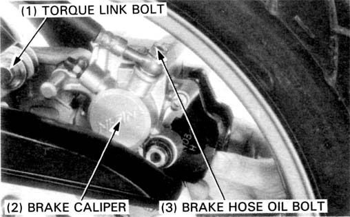
Remove the caliper mounting bolts and torque link bolt.
Remove the brake caliper.
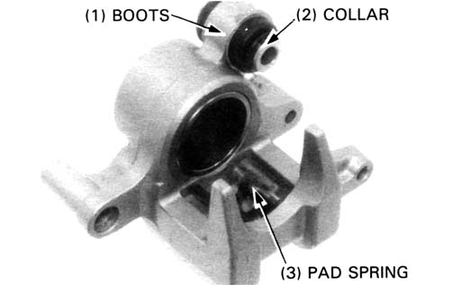
Remove the pad spring, boots and collar from the rear brake caliper.
Place a shop towel over the piston, position the caliper with the piston down and apply small squirts of air pressure to the fluid inlet to remove the piston.
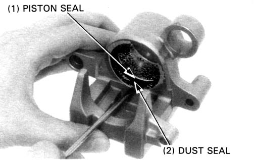
Push the dust and piston seals in and lift them out.
Wash the caliper cylinder, seal grooves and caliper piston with clean brake fluid.
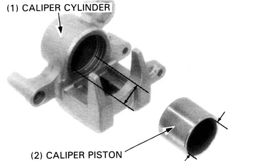
Check the caliper piston for scratches, scoring or other damage.
Measure the caliper cylinder ID
SERVICE LIMIT: 38.24 mm (1.505 in)
Measure the caliper piston OD
SERVICE LIMIT: 38.11 mm (1.500 in)
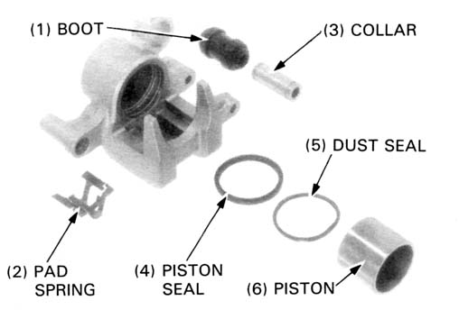
The piston and dust seals must be replaced whenever they are removed.
Check the boot and replace it if it is hardened or deteriorated.
Coat the piston and dust seals with clean brake fluid and install them
with the small diameter facing in.
Lubricate the caliper cylinder and piston with clean brake fluid and install
the piston into the caliper cylinder with the piston dished end facing
toward the pads.
Apply silicone grease to the collar and the insides of the boots and install
them into the caliper.
Make sure that the boot is seated in the collar and caliper grooves properly.
Install the pad spring.
Assemble the bracket and caliper.
Install the pads (page 14-6).
Install the caliper onto the brake disc so the disc is positioned between
the pads, being careful not to damage the pads.
Install the torque link bolt and tighten it.
TORQUE: 35 N•m (3.5 kg-m, 25 ft-lb)
Install the brake hose with the oil bolt and the new sealing washers. Tighten the oil bolt.
TORQUE: 30 N•m (3.0 kg-m, 22 ft-lb)
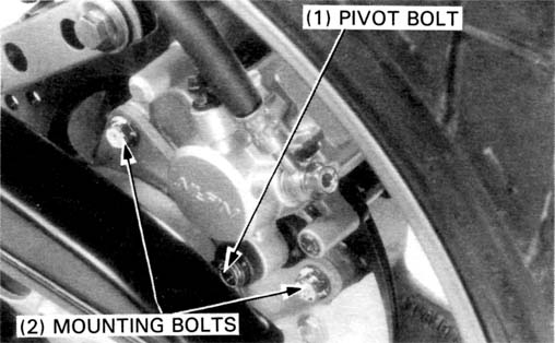
Install the caliper mounting bolts and tighten them.
TORQUE: 27 N•m (2.7 kg-m, 20 ft-lb)
Install the caliper pivot bolt and tighten it.
TORQUE: 22 N•m (2.2 kg-m, 16 ft-lb)
Operate the brake pedal to seat the caliper piston against the pads.
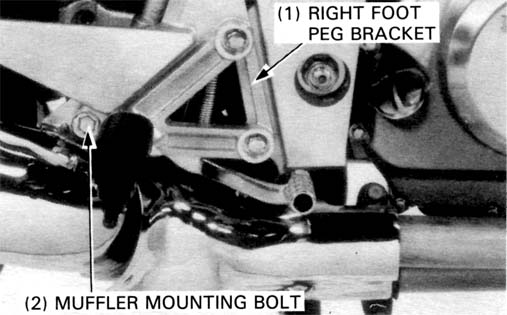
Remove the right foot peg bracket bolts and the muffler mounting bolt and nut.
Remove the cotter pin and joint pin, and disconnect the brake actuating arm from the master cylinder push rod.
Remove the following:
Apply clean grease to the brake pedal pivot and install the pedal into
the bracket with the snap ring.
Installation is the reverse order of removal.
Install the right foot peg bracket. Tighten the mounting bolts.
TORQUE: 22 N•m (2.2 kg-m, 16 ft-lb)
Install the muffler mounting bolt and nut.
TORQUE: 27 N•m (2.7 kg-m, 20 ft-lb)