Hawkworks.net main page
Manual main index
| SERVICE INFORMATION | 3-1 |
EVAPORATIVE EMISSION CONTROL SYSTEM (California model only) | 3-11 |
| MAINTENANCE SCHEDULE | 3-3 | ||
| <ENGINE> | <CHASSIS> | ||
| FUEL LINE | 3-4 | DRIVE CHAIN | 3-12 |
| THROTTLE OPERATION | 3-4 | BRAKE FLUID | 3-13 |
| CARBURETOR CHOKE | 3-5 | BRAKE PAD WEAR | 3-14 |
| AIR CLEANER | 3-5 | BRAKE SYSTEM | 3-14 |
| CRANKCASE BREATHER | 3-6 | BRAKE LIGHT SWITCH | 3-14 |
| SPARK PLUG | 3-6 | HEADLIGHT AIM | 3-15 |
| VALVE CLEARANCE | 3-7 | CLUTCH SYSTEM | 3-15 |
| CARBURETOR SYNCHRONIZATION | 3-8 | SIDE STAND | 3-16 |
| CARBURETOR IDLE SPEED | 3-9 | NUTS, BOLTS, FASTENERS | 3-17 |
| RADIATOR COOLANT | 3-9 | WHEELS/TIRES | 3-17 |
| COOLING SYSTEM | 3-10 | STEERING HEAD BEARINGS | 3-18 |
| CYLINDER COMPRESSION | 3-10 | ||
|
SECONDARY AIR SUPPLY SYSTEM (California model only) | 3-11 | ||
| • Engine oil | see page 2-3 |
| • Engine oil filter change | see page 2-4 |
| Ignition timing | Initial | 10° BTDC at idle | ||
| Full advance | 31° BTDC at 7,000 ± 200 rpm | |||
| Spark plug | NGK | ND | ||
| Standard | DPR8EA-9 | X24EPR-U9 | ||
| For cold climate (below 5° C/41° F) | DPR7EA-9 | X22EPR-U9 | ||
| For extended high speed riding | DPR9EA-9 | X27EPR-U9 | ||
| Spark plug gap | 0.8 – 0.9 mm (0.031 – 0.035 in) | |||
| Valve clearance | IN | 0.15 ± 0.02 mm (0.006 ± 0.0008 in) | ||
| (COLD) | EX | 0.20 ± 0.02 mm (0.008 ± 0.0008 in) | ||
| Idle speed | 1,200 ± 100 rpm | |||
| Cylinder compression | 1,324 ± 196 kPa (13.5 ± 2.0 kg/cm2, 192 ± 28 psi) | |||
| Throttle grip free play | 2 – 6 mm (1⁄16 – ¼ in) | |||
| Clutch lever free play | 10 – 20 mm (3/8 – 3/4 in) |
| Drive train slack | 20 – 30 mm (3/4 – 1-3/16 in) Refer to page 3-12 |
| Front | Rear | ||
| Tire size (Tubeless type) | 110/80-17 57H | 150/70-17 69H | |
| Cold tire pressures kPa (kg/cm2, psi) | Up to 90 kg (200 lbs) | 225 (2.25, 33) | 225 (2.25, 33) |
| Up to maximum weight capacity | 225 (2.25, 33) | 250 (2.50, 36) | |
| Tire brand | Bridgestone Dunlop | G547G K505G | G548 K505 |
| Wheel balance weight | 60g Maximum | 60g Maximum | |
HINT:
There are vastly superior tires available now than in 1988.
Most people use a 110/70-17 front and a 160/60-17 rear.
| Eccentric bearing carrier pinch bolt | 75 N•m (7.5 kg-m, 54 ft-lb) | ||
| Valve adjusting screw lock nut | 23 N•m (2.3 kg-m, 17 ft-lb) | ||
| Timing hole cap | 10 N•m (1.0 kg-m, 7.2 ft-lb) | Apply molybdenum disulfide grease to the threads | |
| Crankshaft hole cap | 15 N•m (1.5 kg-m, 11 ft-lb) | ||
| Spark plug | 14 N•m (1.4 kg-m, 10 ft-lb) | ||
| TOOLS: | |
| Special | |
| Valve adjusting wrench | 07908—KE90000 |
| Vacuum gauge | 07404—0030000 or M937B—021—XXXXX Vacuum gauge set |
The following items require some mechanical knowledge. Certain items (particularly
those marked * and **) may require more technical information and tools. Owners
should consult their authorized Honda dealer.
Perform the PRE-RIDE INSPECTION in the Owner’s Manual at each scheduled
maintenance period.
I: INSPECT AND CLEAN; ADJUST, LUBRICATE OR REPLACE IF NECESSARY.
C: Clean
R: Replace
L: LUBRICATE
| ITEM / FREQUENCY | NOTES | ODOMETER READING (NOTE 1) | |||||||||
| = emissions-related items | x 1,000 mi | 0.6 | 4 | 8 | 12 | 16 | 20 | 24 |
REFER TO
PAGE | ||
| = non-emissions related items | x 100 km | 10 | 64 | 128 | 192 | 256 | 320 | 384 | |||
| * | FUEL LINE | I | I | I | 3-4 | ||||||
| * | THROTTLE OPERATION | I | I | I | 3-4 | ||||||
| * | CARBURETOR CHOKE | I | I | I | 3-5 | ||||||
| AIR CLEANER | (NOTE 2) | R | R | 3-5 | |||||||
| CRANKCASE BREATHER | (NOTE 3) | C | C | C | C | C | C | 3-6 | |||
| SPARK PLUG | R | R | R | R | R | R | 3-6 | ||||
| * | VALVE CLEARANCE | I | I | I | I | 3-7 | |||||
| ENGINE OIL | R | R | R | R | 2-3 | ||||||
| ENGINE OIL FILTER | R | R | R | R | 2-4 | ||||||
| * | CARBURETOR SYNCHRONIZATION | I | I | I | I | 3-8 | |||||
| * | CARBURETOR IDLE SPEED | I | I | I | I | I | I | I | 3-9 | ||
| RADIATOR COOLANT | (NOTE 5) | I | I | *R | 3-9 | ||||||
| * | COOLING SYSTEM | I | I | I | 3-10 | ||||||
| * | SECONDARY AIR SUPPLY SYSTEM | (NOTE 5) | I | I | I | 3-11 | |||||
| * | EVAPORATIVE EMISSION CONTROL SYSTEM | (NOTE 4) | I | I | 3-11 | ||||||
| DRIVE CHAIN | EVERY 600 MI (1,000 km) I. L | 3-12 | |||||||||
| BRAKE FLUID | (NOTE 5) | I | I | *R | I | I | *R | 3-13 | |||
| BRAKE PAD WEAR | I | I | I | I | I | I | I | 3-14 | |||
| BRAKE SYSTEM | I | I | I | I | 3-14 | ||||||
| * | BRAKE LIGHT SWITCH | I | I | I | 3-14 | ||||||
| * | HEADLIGHT AIM | I | I | I | 3-15 | ||||||
| CLUTCH SYSTEM | I | I | I | I | I | I | I | 3-15 | |||
| SIDE STAND | I | I | I | 3-16 | |||||||
| * | SUSPENSION | I | I | I | 3-16 | ||||||
| * | NUTS, BOLTS, FASTENERS | I | I | I | I | 3-17 | |||||
| ** | WHEELS/TIRES | I | I | I | I | I | I | I | 3-17 | ||
| ** | STEERING HEAD BEARINGS | I | I | I | I | 3-18 | |||||
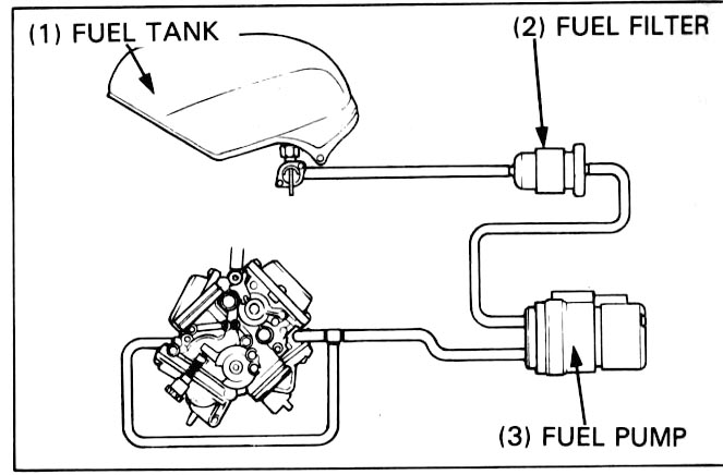
Remove the seat (page 13-25).
Check the fuel lines for deterioration, damage or leakage.
Replace the fuel lines if necessary.
Check for smooth throttle grip full opening and automatic full closing in all
steering positions.
Check the throttle cables and replace them if they are deteriorated, kinked
or damaged.
Lubricate the throttle cables, if throttle operation is not smooth.
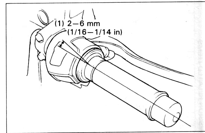
Measure the free play at the throttle grip flange.
FREE PLAY: 2 – 6 mm (1/16 – 1/4 in)
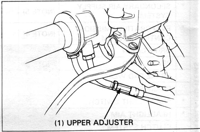
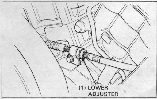
Throttle grip free play can be adjusted at either end of the throttle cable. Minor adjustments are made with the upper adjuster.
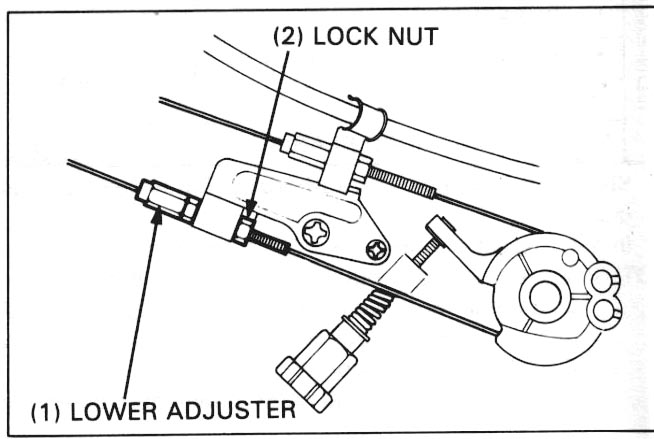
Major adjustments are made with the lower adjuster.
Adjust the free play by loosening the lock nut and turning the adjusting nut.
Tighten the lock nuts.
Recheck throttle operation. Replace any damaged parts, if necessary.
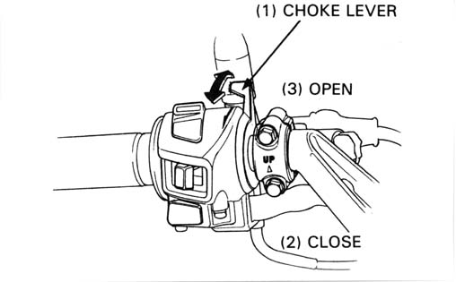
This model’s choke system uses a fuel enrichening circuit controlled by a choke valve. The choke valve opens the enrichening circuit via a cable when the choke lever on the handlebar is pulled back.
Check for smooth upper choke lever operation. Lubricate the choke cable if the operation is not smooth.
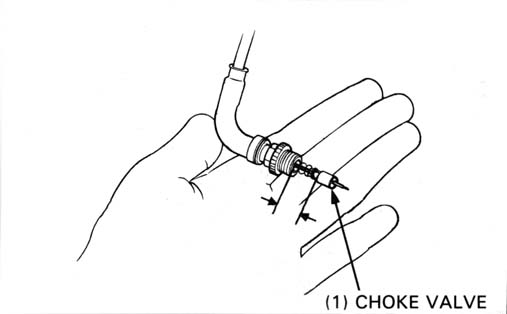
Remove the left and right choke cable boots from the choke valve nuts.
Loosen each choke valve nut and remove the choke valve from the carburetor.
Push the choke lever on the handlebar all the way up to fully closed and measure the distance between the ends of the choke valve and nut. It should be 10- 11 mm (0.39-0.43 in).
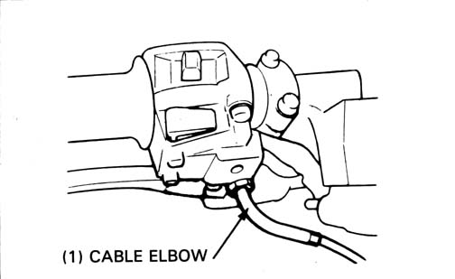
Adjust the distance to within specifications by loosening the lock nut and
turning the cable’s elbow at the left handlebar switch housing.
Tighten the lock nut securely and recheck the distance.
Thread the choke valve in by hand and then tighten the choke valve nut 1/4 turn with a 14 mm wrench.
Remove the fuel tank (page 4-3).
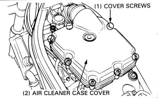
Remove the air cleaner case cover screws and cover
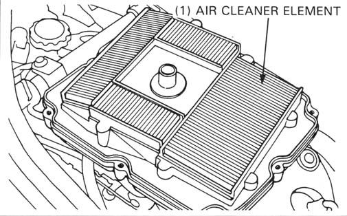
Remove the air cleaner element.
Replace the element in accordance with the maintenance schedule.
Also, replace the element any time it is excessively dirty or damaged.
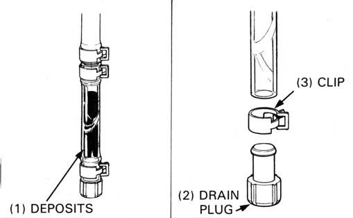
The crankcase breather drain; air cleaner case drain tube is behind the side stand.
Remove the drain plug from the tube to empty any deposits. Reinstall the plug securely.
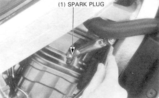
Disconnect the spark plug caps and remove the spark plugs.
RECOMMENDED SPARK PLUG:
| NGK | ND | |
| Standard | DPR8EA-9 | X24EPR-U9 |
| For cold climate (below 5°C/41°F) | DPR7EA-9 | X22EPR-U9 |
| For extended high-speed riding | DPR9EA-9 | X27EPR-U9 |
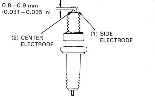
Measure the new spark plug gap with a wire-type feeler gauge.
SPARK PLUG GAP: 0.8-0.9 mm (0.031-0.035 in)
Adjust the gap if necessary, by bending the side electrode carefully.
With the plug washer attached, thread each spark plug in by hand to prevent
crossthreading. Continue tightening by hand until the spark plug bottoms.
Then, tighten the spark plugs another 1/2 turn with a spark plug wrench
to compress the plug washer.
TORQUE: 14 N•m (1.4 kg-m, 10 ft-lb)
Connect the spark plug caps.
Install the removed parts in the reverse order of removal.
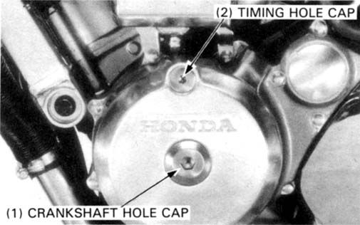
Remove the following parts:
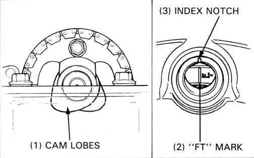
FRONT CYLINDER
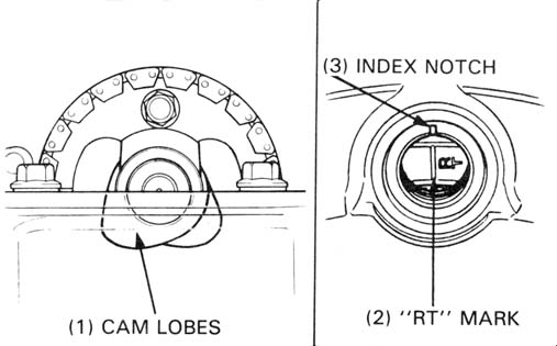
Rotate the flywheel counterclockwise to align the “FT” mark with the index notch on the left crankcase cover. Make sure the piston is at TDC (Top Dead Center) on the compression stroke and the cam lobes are all facing down as shown.
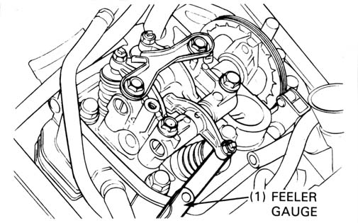
Inspect the clearance of all three valves by inserting a feeler gauge between the adjusting screw and the valve.
| VALVE CLEARANCES: (COLD) | ||
| Intake: | 0.15 ± 0.02 mm (0.006 ± 0.0008 in) | |
| Exhaust: | 0.20 ± 0.02 mm (0.008 ± 0.0008 in) | |
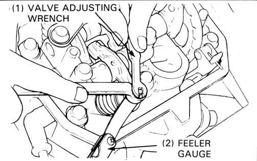
Adjust by loosening the lock nut and turning the adjusting screw until there is a slight drag on the feeler gauge.
Apply oil to the nut and screw threads.
Hold the adjusting screw and tighten the lock nut.
| TOOL: | |
| Valve adjusting wrench | 07908—KE90000 |
TORQUE: 23 N•m (2.3 kg-m, 17 ft-lb)
REAR CYLINDER
Rotate the flywheel counterclockwise to align the "RT" mark with the index notch on the left crankcase cover. Make sure the piston is at TDC on the compression stroke and the cam lobes are all facing down.
Inspect and adjust the valve clearance using the same method as for the
front cylinder.
Install the front and rear cylinder head covers.
Apply molybdenum disulfide grease to the threads of the timing and crankcase
hole caps, then install and tighten them.
TORQUE:
Timing hole cap:
10 NM (1.0 kg-m, 7.2 ft-lb)
Crankshaft hole cap:
15 NM (1.5 kg-m, 11 ft-lb)
Remove the rear fuel tank mounting bolt first, then remove the front side (page 4-3). Carefully raise the tank and support it in the frame using a suitable base.
FRONT CYLINDER:
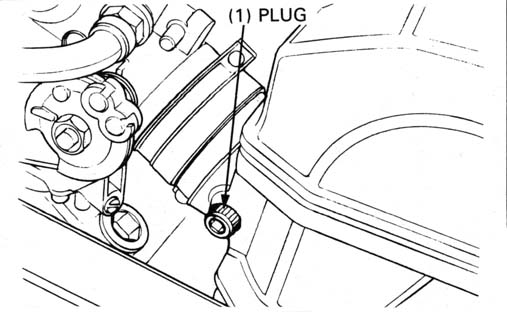
Remove the plug from the front cylinder intake port and install the vacuum
gauge adapter.
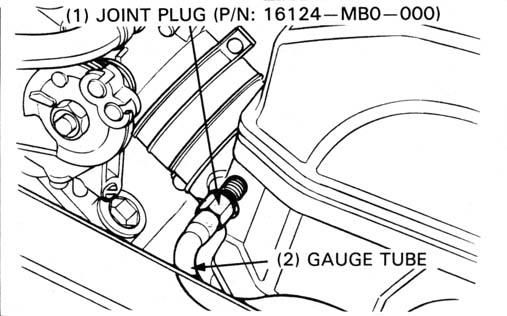
REAR CYLINDER:
Remove the plug from the rear cylinder intake port and install the joint
plug (P/N: 16124-MBO-000).
Connect the vacuum gauge tube and vacuum gauge.
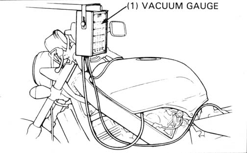
| TOOL: | |
| Vacuum gauge | 07404—0030000 or |
| Vacuum gauge set | M937B—021—XXXXX |
Warm up the engine and adjust the idle speed with the throttle stop screw.
IDLE SPEED: 1,200 ± 100 rpm

Check that the difference in vacuum readings is 40 mm (1.6 in) Hg or less.
If necessary, synchronize to the specification by turning the synchronization adjusting screw.
Recheck the idle speed and synchronization. Disconnect the gauge and adapters and install the removed parts.
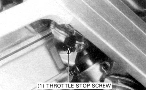
Warm up the engine, shift to NEUTRAL, and place the motorcycle on its center stand.
Turn the throttle stop screw as required to obtain the specified idle speed.
IDLE SPEED: 1,200 ± 100 rpm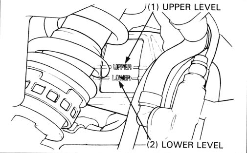
Check the coolant level of the reserve tank with the engine running at normal operating temperature.
NOTE: Engine HOT, not cold!!
The level should be between the “UPPER” and “LOWER” level lines.
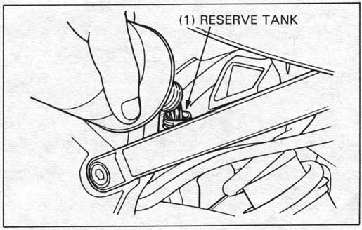
If necessary, remove the reserve tank cap. Fill up to the upper level line with 50/50 mixture of distilled water and antifreeze.
Reinstall the reserve tank cap.
HINT: Despite what this picture shows, there’s no way you’ll be able to pour coolant into the reserve tank without a funnel.
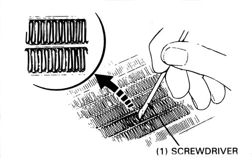
Remove the radiator shroud and check the radiator air passages for
clogging or damage.
Straighten bent fins or collapsed core tubes with a small flat blade screwdriver
as shown and remove insects, mud or any obstructions with compressed air
or low-pressure water.
Replace the radiator if the air flow is restricted over more than 30%
of the radiator’s surface.
For radiator replacement, refer to page
5-5.
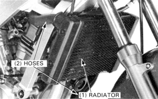
Make sure the hoses are in good condition.
Replace any hose that shows any sign of deterioration.
Check that all hose clamps are tight.
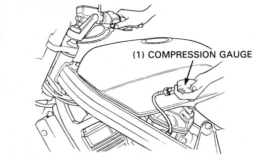
Warm up the engine to normal operating temperature.
Stop the engine, disconnect both spark plug caps and remove one spark plug.
Turn the engine stop switch OFF.
Insert the compression gauge. Open the throttle all the way and crank the engine with the starter motor. Crank the engine until the gauge reading stops rising. The maximum reading is usually reached within 4-7 seconds.
COMPRESSION PRESSURE:
1,324 ± 196 kPa (13.5 ± 2.0 kg/cm2,
192 ± 28 psi)
If compression is high, it indicates that carbon deposits have accumulated on the combustion chamber and/or the piston crown.
If compression is low, pour 3-5 cc (0.1 - 0.2 US. oz) of clean engine oil into the cylinder through the spark plug hole and recheck the compression.
If the compression increases from the previous value, check the cylinder,
piston and piston rings.
If the compression is the same as the previous value, check the valves
for leakage.
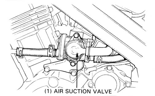
Check the air and vacuum hoses and tubes for bending or twisting and straighten if necessary.
Check the system hoses and tubes for damage, deterioration, clogging or loose connections. Check the air suction valve for damage ( page 4-17). Refer to the vacuum hose routing diagram label for hose connections as shown below.
Check the hoses between the fuel tank, canister, purge control valve (PCV), air vent control valve (AVCV), and carburetor for deterioration, damage or loose connections.
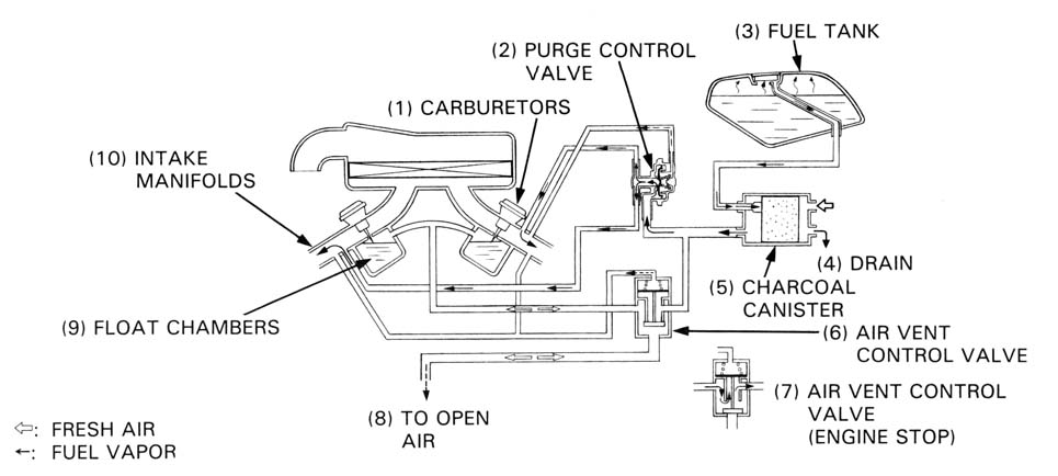
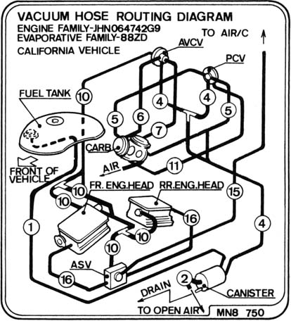
Also check the tubes for bending or twisting
and straighten if necessary.
Check the canister for cracks deterioration, or other damage. Refer to the
vacuum hose routing diagram label for connections as shown right.
Turn the ignition switch OFF, support the motorcycle on its
center stand and shift the transmission into neutral.
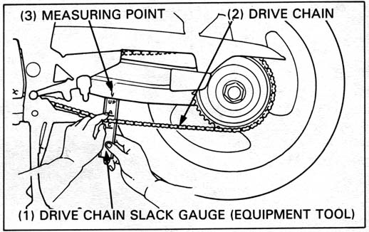
Place the chain slack gauge against the reference arrow
on lower edge of the swingarm as shown.
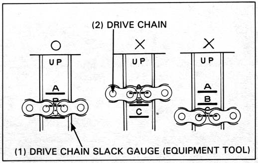
Pull the lower run of the drive chain down with your finger and check slack using the gauge.
| A-B: | Good. |
| Above A: | Too tight. |
| Below C: | Too loose. |
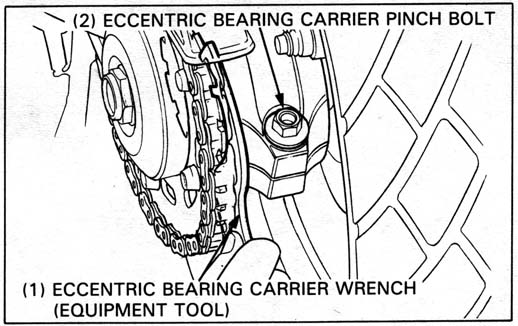
Loosen the eccentric bearing carrier pinch bolt.
Turn the eccentric bearing carrier clockwise or counterclockwise by the bearing
carrier wrench to obtain the drive chain slack as necessary.
Tighten the eccentric bearing carrier pinch bolt.
TORQUE: 75 N•m (7.5 kg-m, 54 ft-lb)
Recheck chain slack.
Lubricate the drive chain with SAE #80 or 90 gear oil.
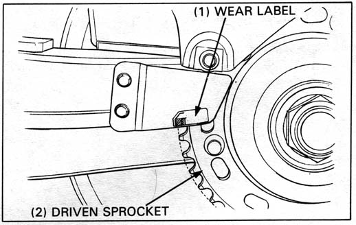
Check the chain wear label on the swingarm. If the red zone on the label aligns with the driven sprocket teeth after chain has been adjusted, the chain must be replaced.
| REPLACEMENT CHAIN: | RK525 SM3 or DID525 V7 (112 LE) |
| LINK: | 112 Links |
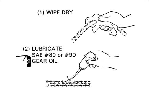
LUBRICATION AND CLEANING
When the drive chain becomes extremely dirty, it should be cleaned prior
to lubrication.
Clean the drive chain with a non-flammable or high flash point and wipe
dry.
The drive chain on this motorcycle is equipped with small 0-rings between the link plates. The O-rings can be damaged by steam cleaners, high-pressure washers and certain solvents.
Lubricate only with SAE #80 or 90 gear oil.
Commercial chain lubricants
may contain solvents which could damage the rubber O-rings.
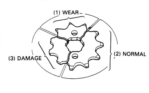
DRIVE AND DRIVEN SPROCKET
Inspect the sprocket teeth for excessive wear or damage. Replace if necessary.
FRONT
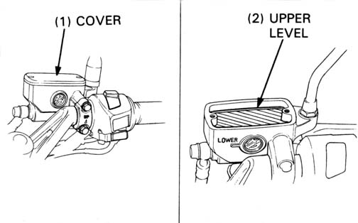
Check the front brake fluid level with the handlebar turned so that the
reservoir is level.
Check the front brake fluid through the sight glass. If the level is visible,
check pad wear first; replace the pads if necessary. Then remove the cover,
set plate and diaphragm. Fill the reservoir to the upper level with DOT
4 fluid from a sealed container. Check the system for leaks.
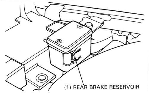
REAR
Check the rear brake fluid level after supporting the motorcycle upright
on level ground.
Check the rear brake fluid level; if it is near the lower line, check
pad wear first; replace the pads if necessary. Then remove the cover,
set plate and diaphragm. Fill the reservoir to the upper level with DOT
4 fluid from a sealed container. Check the system for leaks.
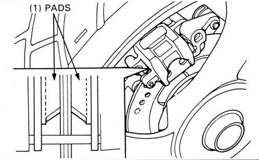
FRONT
Check the front brake pads for wear, through from the lower end of the caliper.
REAR
Check the rear brake pads for wear, through from the rear of the caliper.
See section 14 for brake pad replacement.
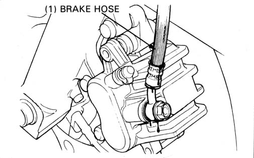
Inspect the brake hoses and fittings for deterioration, cracks and signs of leakage. Tighten any loose fittings. Replace hoses and fittings as required.
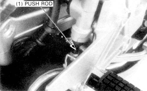
REAR BRAKE PEDAL
Check the rear brake pedal height.
To adjust the brake pedal height,
loosen the lock nut and turn the master cylinder push rod. Tighten the
lock nut.
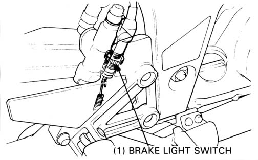
Adjust the brake light switch so that the brake light will come on when
brake engagement begins.
Adjust by turning the adjuster while holding the switch body. Tighten
the adjuster lock nut and recheck the brake light switch operation.
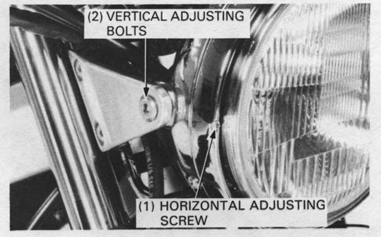
Adjust vertically by loosing the headlight mounting bolts.
Adjust horizontally by turning the horizontal adjusting screw.
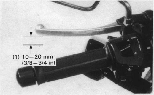
Measure the clutch lever free play at the lever end.
FREE PLAY: 10 - 20 mm (3/8 - 3/4 in)
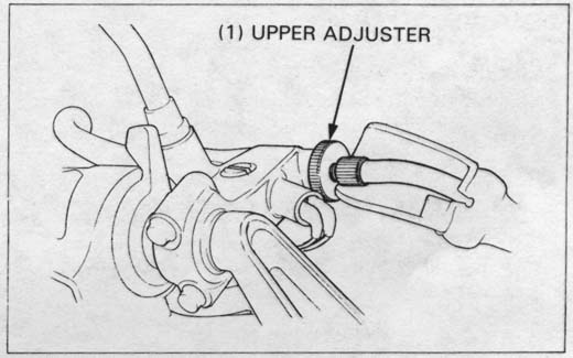
Minor adjustments are made with the upper adjuster.
Pull the lever cover back, loosen the lock nut and turn the adjuster to obtain the specified free play.
Tighten the lock nut and install the cover.
Check clutch operation.
Major adjustments are made with the lower adjuster.
Loosen the lock nut and turn the adjusting nut to obtain the specified
free play.
Tighten the lock nut and check the clutch operation.
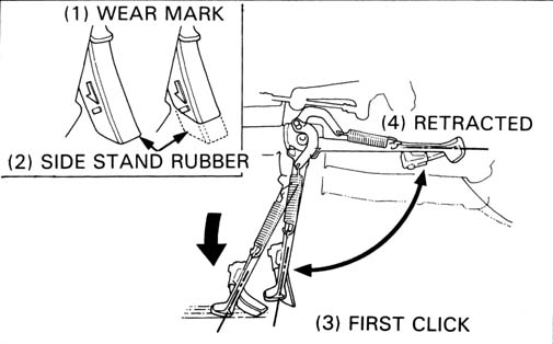
If the side stand does not operate smoothly, disassemble and check the
side stand assembly as following procedure:
Remove the return spring at the retracted position.
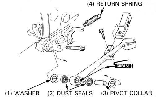
Remove the pivot bolt and side stand.
Check the following parts:
— inside of the pivot and pivot collar for wear or damage.
— pivot dust seal for damage.
Lubricate the pivot area with clean grease and reassemble the side stand.
Check the side stand operation as indicated above.
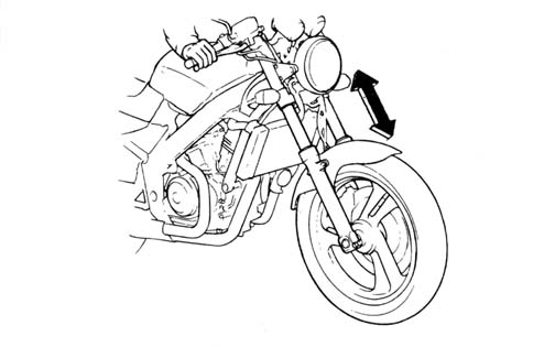
FRONT
Check the suspension action by compressing it several times.
Check the entire fork leg assembly for signs of leaks or damage.
Replace any components which are unrepairable. Tighten all nuts and bolts
to the specified torque value.
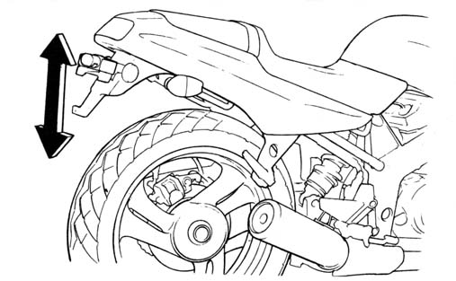
Place the motorcycle on its center stand.
Check for worn swingarm bearings by grabbing the swingarm, and attempting
to move the swingarm side to side.
Replace the bearings if any looseness is noted
(page 13-19).
Tighten all nuts and bolts.
Tighten the bolts, nuts and fasteners at the intervals shown in the Maintenance
Schedule (page 3-3).
Check that all chassis nuts and bolts are tightened to their correct torque values
(page 1-5 and 6).
Check all cotter pins and safety clips.
| Front | Rear | ||
| Tire size (Tubeless type) | 110/80-17 57H | 150/70-17 69H | |
| Cold tire pressures kPa (kg/cm2, psi) | Up to 90 kg (200 lbs) | 225 (2.25, 33) | 225 (2.25, 33) |
| Up to maximum weight capacity | 225 (2.25, 33) | 250 (2.50, 36) | |
| Tire brand | Bridgestone Dunlop | G547G K505G | G548 K505 |
| Wheel balance weight | 60g Maximum | 60g Maximum | |
HINT:
There are vastly superior tires available now than in 1988.
Most people use a 110/70-17 front and a 160/60-17 rear.
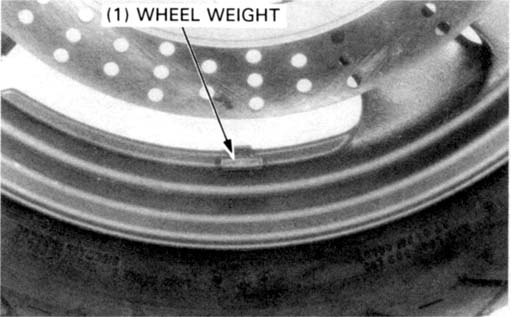
Check the tires for cuts, imbedded nails, or other sharp objects.
Check the front and rear wheels for trueness ( Section 12 and 13).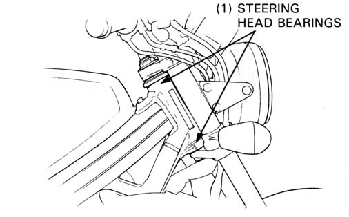
Raise the front wheel off the ground.
Check that the fork pivots freely from side to side. If the fork pivots
unevenly, binds, or has vertical movement, inspect the steering head bearings
(Section 12).