Hawkworks.net main page
Manual main index
| SERVICE INFORMATION | 18-1 |
| TROUBLESHOOTING | 18-2 |
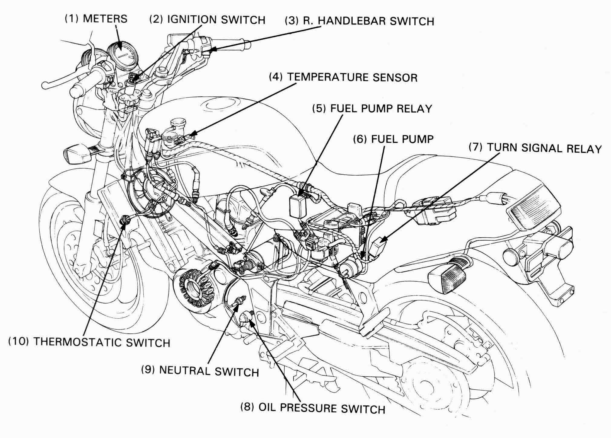
| SWITCHES LOCATION | 18-2 |
| HEADLIGHT | 18-3 |
| IGNITION SWITCH/METER | 18-4 |
| HANDLEBAR SWITCHES | 18-6 |
| THERMOSTATIC SWITCH | 18-7 |
| TEMPERATURE SENSOR | 18-7 |
| TEMPERATURE GAUGE | 18-8 |
| FUEL PUMP RELAY | 18-8 |
| FUEL PUMP | 18-9 |
| OIL PRESSURE SWITCH | 18-9 |
| NEUTRAL SWITCH | 18-9 |
| TURN SIGNAL RELAY | 18-10 |
| Headlight | 12V 60W/55W | H4 / HB2 / 9003 | |
| Brake/taillight | 12V 32/3 cp (27/8 W) x2 | 1157 | |
| Turn signal lights | Front | 12V 32/3 cp (23/8 W) x2 | 1157 |
| Rear | 12 V 32 cp (23 W) | 1156 | |
| License light | 12V, 8W, 4cp | 34616-568-671, 1195, 1155, 97 | |
| Indicator lights | Turn signal | 12V 3W | 34908-KM1-671 |
| Neutral | 12V 3W | 34908-KM1-671 | |
| High beam | 12V 3W | 34908-KM1-671 | |
| Meter light | 12v 3.4W x1, 1.7W x2 | 34908-MG9-951 or 34908-MN8-700 | |
| Main Fuse | 30A | ATO type fuse | |
| Sub-fuse | fan | 10A | |
| Ignition | 10A | ||
| Headlight | 10A | ||
| Oil/neutral | 10A | ||
| Brake/turn/horn | 15A | ||
| Parking | 10A | ||
| Fuel pump flow capacity/min | 600cc (0.630 US qt, 0.528 Imp qt) | ||
| Radiator thermostatic switch | 18 N•m (1.8 kg-m, 13 ft-lb) — Apply sealant to threads | |
| Oil Pressure Switch | 12 N•m (1.2 kg-m, 9 ft-lb)— Apply sealant to threads | |
| Ignition switch mounting bolt | 25 N•m (2.5 kg-m, 18 ft-lb) |
Common
T-40 Torx bit07703—0010100 — Equivalent commercially available in U.S.A.
No Lights Come On When Ignition Switch Is Turned On:
All Lights Come On, but Dimly, when Ignition Switch Is Turned ON
Headlight Beam Does Not Shift When HI-LO Switch Is Operated:
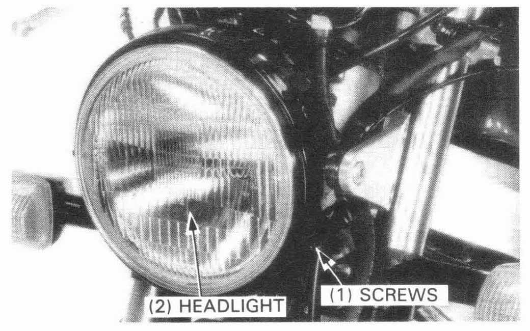
Remove the two screws and headlight.
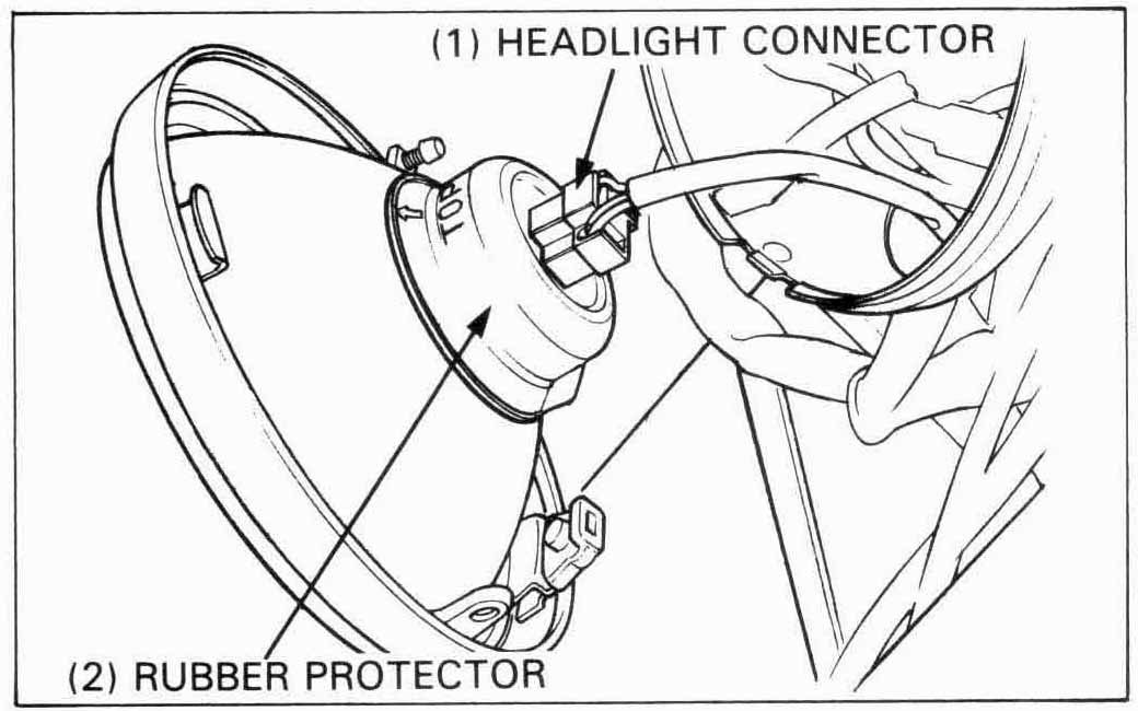
Disconnect the headlight connector and remove the rubber protector.
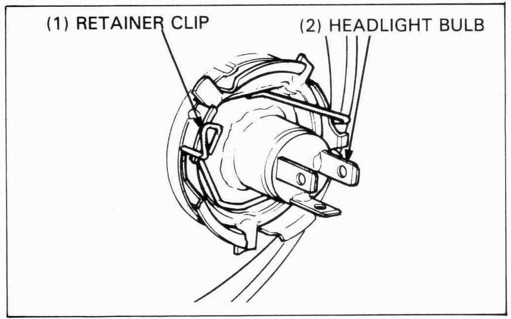
Remove the headlight retainer clip and replace the headlight bulb.
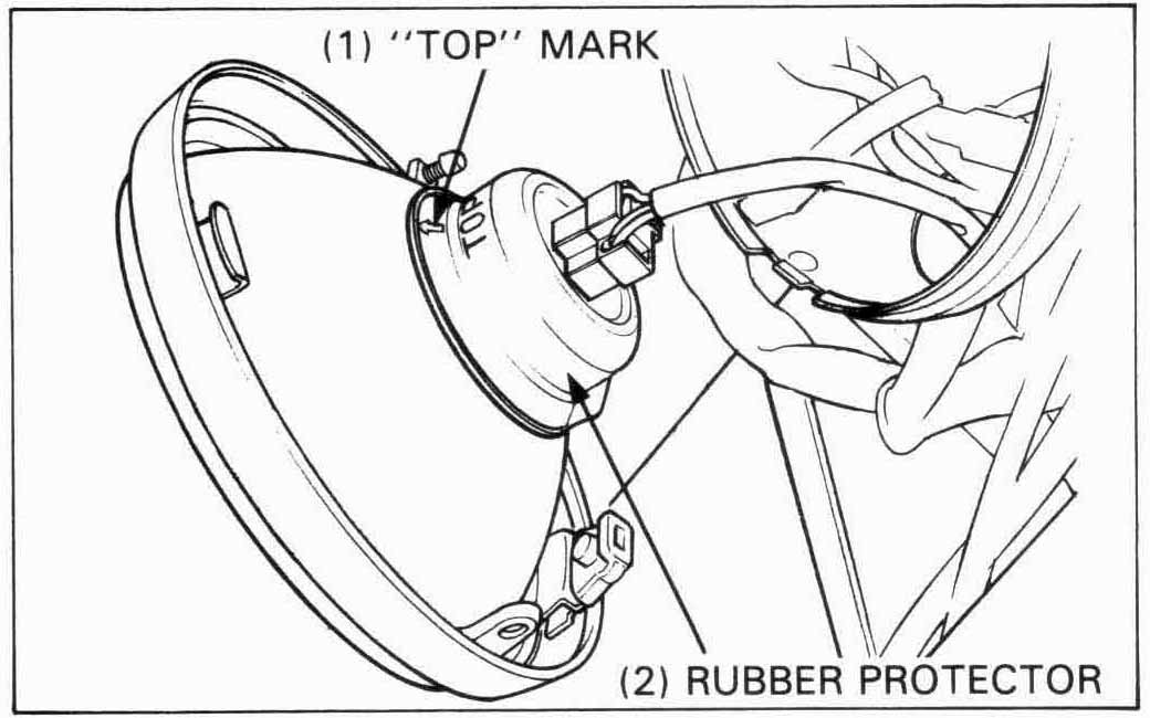
Install the headlight in the reverse order of removal.
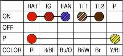
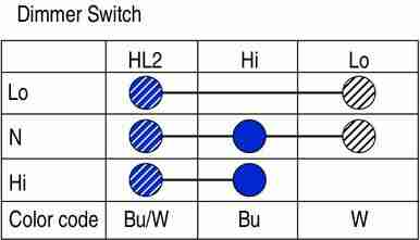
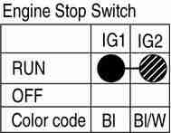
Check for continuity between the ignition switch connector terminals in each switch position.
Continuity should exist between the color coded wires as shown in the chart below.
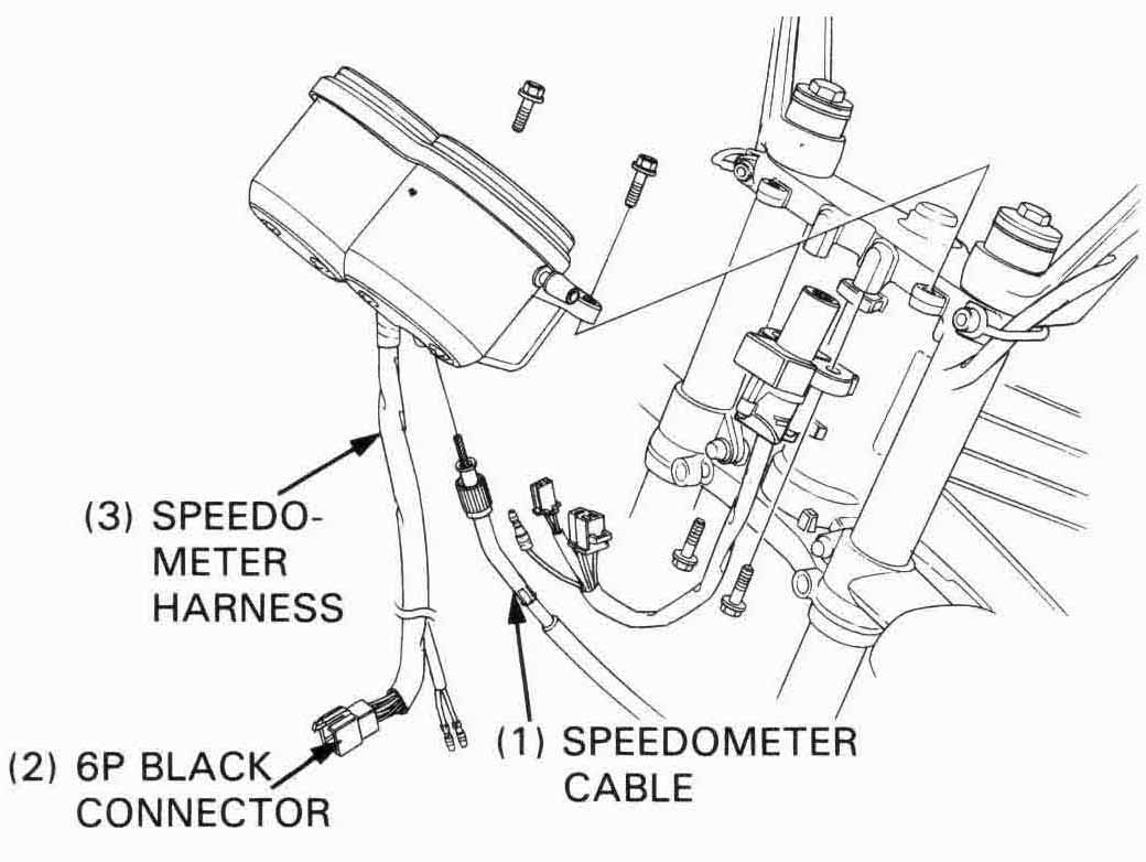
Disconnect the speedometer cable from the meter cover.
Remove the headlight.
Disconnect the meter harness connectors and ignition switch
connectors in the headlight case.
Remove the mounting bolts and meters.
’88 Only:
Remove the mounting bolts and ignition switch.
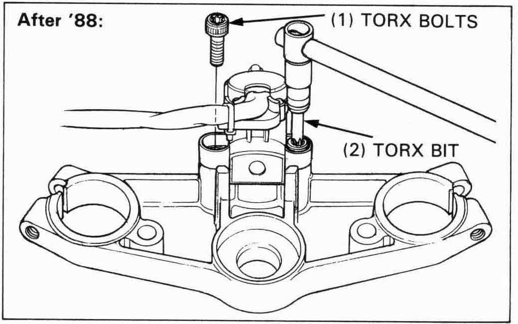
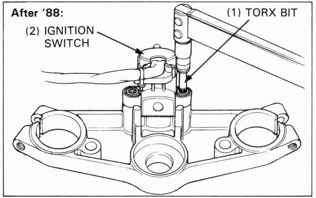
After ’88:
Remove the (torx) mounting bolts using the special tool and
the ignition switch.
| TOOL: | |
| T-40 Torx bit | 07703—0010100 or equivalent commercially available in U.S.A. |
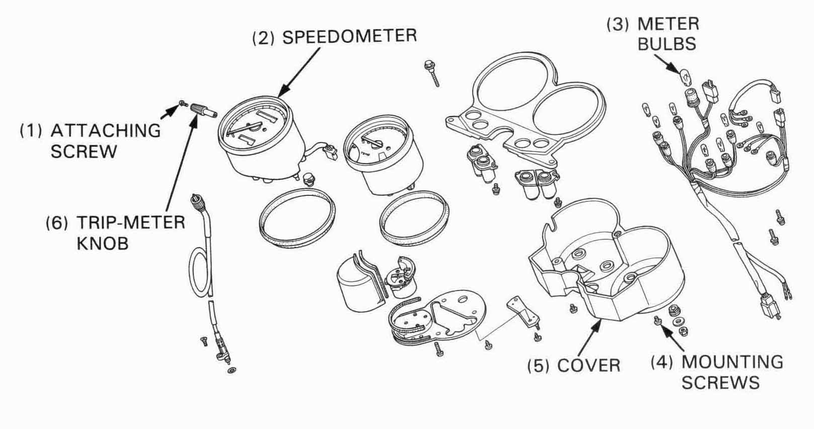
Remove the meter cover mounting screws and cover.
Replace the burned bulb(s) as required.
Assemble the removed parts in the reverse order of disassembly.
After ’88:
Install the meters and ignition switch in the reverse
order of removal.
After ’88:
Install the meters in the reverse order of removal.
Install the ignition switch and tighten the torx bolts using the special tool.
| TOOL: | |
| T-40 Torx bit | 07703—0010100 or equivalent commercially available in the U.S.A. |
| TORQUE: Ignition switch mounting bolt | |
| 25 N•m *2.5 kg-m, 18 ft-lb) | |
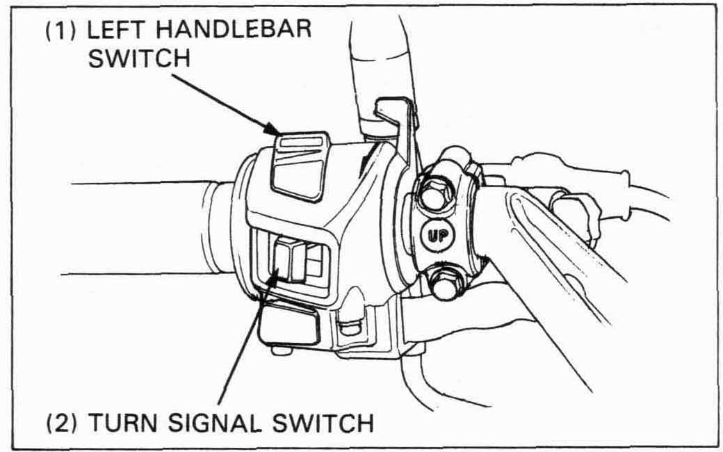
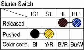
The handlebar switches (dimmer, turn signals, horn, starter,
engine stop, etc.) must be replaced as assemblies.
Remove the headlight.
Disconnect the left handlebar switch connector (9P White).
And check for continuity between the terminals.
Continuity should exist between the color coded wires in
each chart.
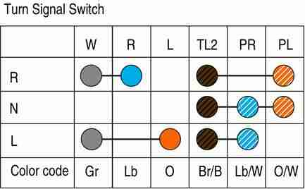
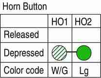
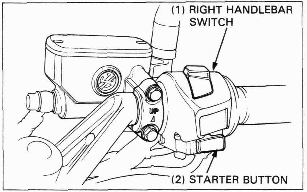
Disconnect the right handlebar switch connector (9P Red) and
check for continuity between the terminals.
Continuity should exist between the color coded wires as indicated
in each chart.
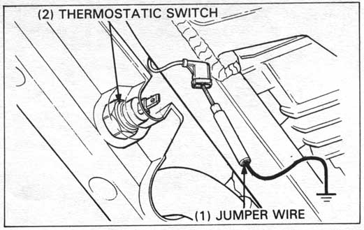
If the fan motor does not start, disconnect the Black/Blue
lead from the thermostatic switch and ground it with a
jumper wire as shown.
Turn the ignition switch ON. The cooling fan motor should start
running. If it does not start, check for battery voltage from
the Black/Blue lead of the fan motor connector and ground with
ignition switch ON.
If there is no voltage, check for a blown fuse, loose terminals
or connectors, or an open circuit.
If there is voltage, inspect the thermostatic switch as follows:
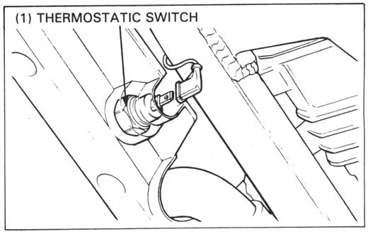
Remove the switch.
Connect one lead of an ohmmeter to the connector of the thermostatic
switch and the other to the body.
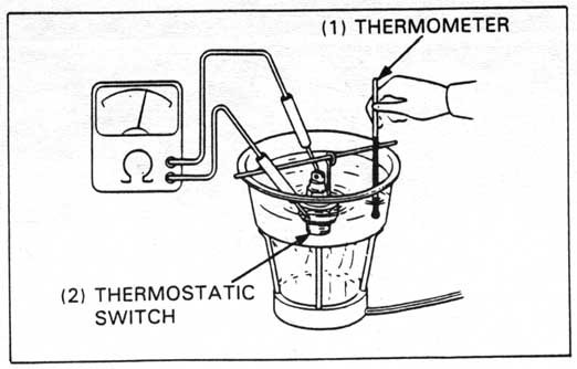
Suspend the thermostatic switch in a pan of coolant (50-50 mixture)
and check the temperatures at which the switch opens and closes.
Make sure that there is no continuity at room temperature and then
gradually raise the coolant temperature. The switch should show
continuity (close) at 93°-97°C (199°-207° F).
TORQUE: 18 N•m (1.8 kg-m, 13 ft-lb)
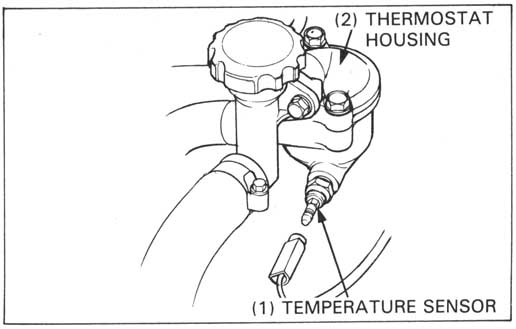
Remove the seat and fuel tank.
Disconnect the Green/Blue wire from the temperature sensor.
Check for continuity between the sensor body and ground.
There should be continuity.
If there is no continuity, check the thermostat housing for
looseness and recheck. If there is still no continuity, remove.
The temperature sensor from the thermostat housing.
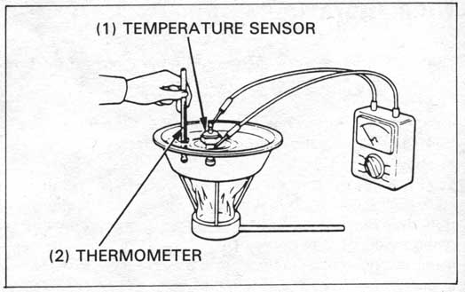
Suspend the temperature sensor in a pan of coolant over a heater and measure the resistance through the sensor as the coolant heats up.
| Temperature | 50°C (122°F) | 100°C (212°F) |
| Resistance | 130-180 Ohm. | 25-30 Ohm. |
Replace the sensor if it is out of specification by more than 10% at either temperature.
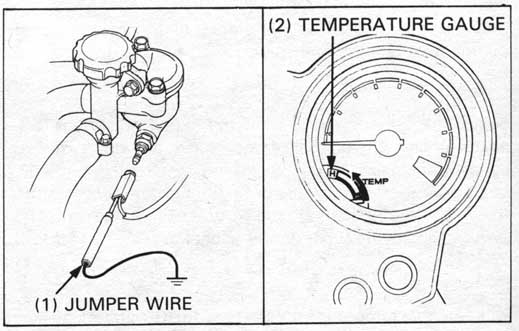
Disconnect the wire from the temperature sensor and short it to ground.
Turn the ignition switch ON. The temperature gauge needle should move all the way to (H).
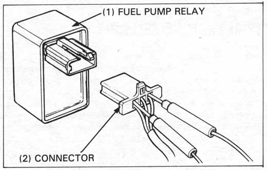
Remove the seat.
Check the sub-fuse (10 A).
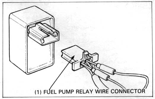
Remove the relay from the rubber bracket and check the relay
connector terminals for looseness and corrosion.
Inspect as follows:
Disconnect the connector and test the wires on the main harness side.
| ITEM | STANDARD |
|---|---|
| Between Bl (+) and body ground (-) with the ignition switch "ON" | Battery voltage should come. |
| Y/Bu wire between the pump relay and spark unit | CONTINUITY |
| Bl/Bu wire between the pump relay and fuel pump | CONTINUITY |
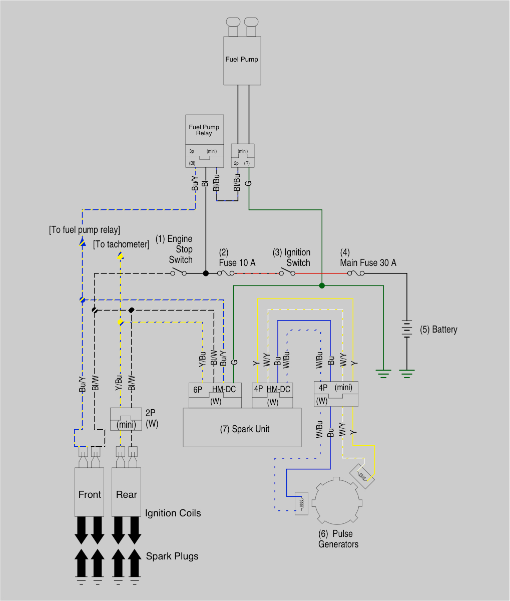
HINT: Here is a full wiring diagram of how the fuel pump is powered
Turn the ignition switch OFF. Remove the seat and disconnect the fuel pump relay wire connnectors. Short the black and black/blue wire terminals with a wire jumper wire.
Disconnect the fuel tube from the T-joint near the carburetor and hold a graduated beaker under the fuel tube.
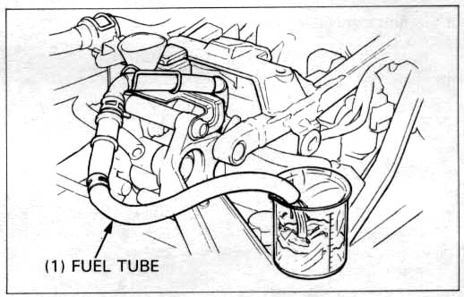
Turn the ignition switch ON and let fuel flow into the beaker for 5 seconds, then turn the
ignition switch OFF.
Multiply the amount in the beaker by 12 to determine the fuel pump flow capacity per minute.
FUEL PUMP FLOW CAPACITY:
600 cc (0.630 US qt. 0.528 Imp qt) /minutes at 10 V
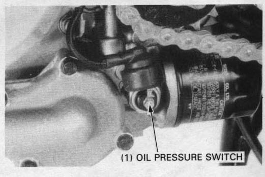
Make sure that the oil pressure warning light comes on with the ignition switch "ON".
If the light does not come on, inspect as follows:
Remove the drive sprocet cover.
Disconnect the oil pressure switch wire from the switch by removing the terminal screw.
Short it to ground using a jumper wire.
Turn the ignition switch "ON".
The oil pressure warning light should come on.
If the light does not come on, check the bulb, sub-fuse (10A) and wires for a loose
connection or an open circuit.
Start the engine and make sure that the light goes out. If the light does not go out,
check the oil presure (page 2-4).
If the oil pressure is normal, replace the oil pressure switch. (page 2-4)
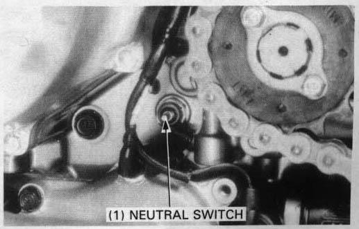
Remove the drive sprocket cover and disconnect the connector.
Check the neutral switch for continuity between the light green/red connector and body ground.
There should be continuity with the transmission in neutral and no continuity with the
transmition in any gear.
If there is no continuity in neutral, remove the drive sprocket cover (page 8-2) and check the
wire connection for an open circuit.
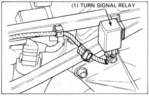
Remove the seat and
rear cowling (pages 13-25).
Remove the turn signal relay from the rubber bracket.
Check the turn signal circuit for proper connections before making this test.
Check each terminal as indicated below:
| White/Green: | D.C. 12 V Positive (+) |
| Green: | D.C. 12 V Negative (-) |
| Gray: | Turn signal wire of one side; connect the other side to ground (frame). |
Check the left and right turn signal operation.
If the turn signal relay fails this test, replace it.
HINT: Here is a full wiring diagram of how the turn signals and dash indicator are powered, and how to deal with LED replacement signals.