Hawkworks.net main page
Manual main index
| GENERAL SAFETY | 1-1 |
| SERVICE RULES | 1-1 |
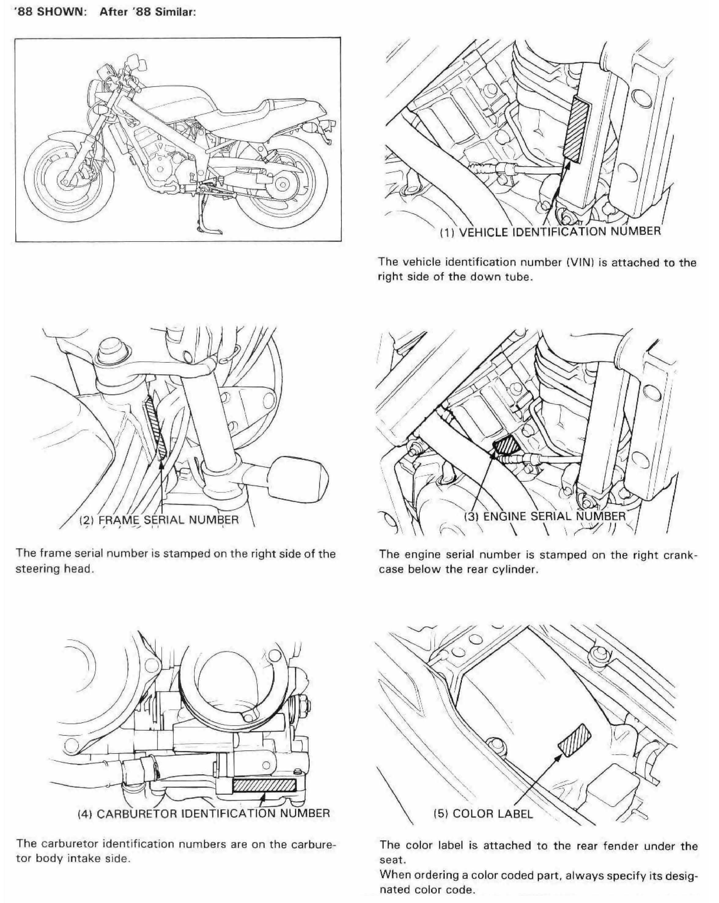
| MODEL IDENTIFICATION | 1-2 |
| SPECIFICATIONS | 1-3 |
| TORQUE VALUES | 1-5 |
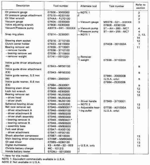
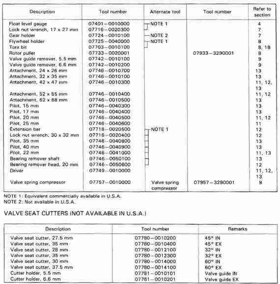
| TOOLS | 1-7 |
| CABLE & HARNESS ROUTING | 1-9 |
| EMISSION CONTROL SYSTEMS | 1-16 |
| EMISSION CONTROL INFORMATION LABELS | 1-18 |
| ITEM | SPECIFICATION | |||||||||||||||||||||||||||||||||||||||
|---|---|---|---|---|---|---|---|---|---|---|---|---|---|---|---|---|---|---|---|---|---|---|---|---|---|---|---|---|---|---|---|---|---|---|---|---|---|---|---|---|
| DIMENTIONS |
|
| ||||||||||||||||||||||||||||||||||||||
| FRAME | Type Front suspension, travel Rear suspension, travel Gross vehicle weight rating Maximum weight capacity Front tire size Rear tire size | Twin tube diamond, aluminum Telescopic fork, 130 mm (5.12 in) Swingarm, 120 mm (4.72 in) 291 kg (642 lb) 156 kg (345 lb) 110/80-17 57H Tubless type 150/70-17 69H Tubless type | ||||||||||||||||||||||||||||||||||||||
| Cold Tire Pressure | Up to 90 kg (200 lb) load | Front Rear | 225 kPa (2.25 kg/cm2, 33 psi) 225 kPa (2.25 kg/cm2, 33 psi) | |||||||||||||||||||||||||||||||||||||
| Up to macimum weight capacity | Front Rear | 225 kPa (2.25 kg/cm2, 33 psi) 250 kPa (2.50 kg/cm2, 36 psi) | ||||||||||||||||||||||||||||||||||||||
|
Front brake, lining swept area Rear brake, lining swept area Fuel capacity Fuel reserve capacity Caster angle Trail length Fork oil capacity ’88 after ’88 Fork oil level ’88 after ’88
| Hydraulic single disk, 262 x 2 cm2 (40.6 x 2 sq in) Hydraulic single disk, 200 x 2 cm2 (31.0 x 2 sq in) 12.0 lit (3.18 US gal, 2.64 Imp gal) 2.0 lit (2.10 US qt, 1.76 Imp qt) 27° 111 mm (4.37 in) 497 cc (16.8 US oz, 17.4 Imp oz) 502 cc (16.9 US oz, 17.6 Imp oz) 133 mm (5.2 in) 128 mm (5.0 in) | |||||||||||||||||||||||||||||||||||||||
| ENGINE | Type Cylinder arrangement Bore and stroke Displacement Compression Ratio Valve train Oil Capacity after disassembly: Coolant change: Air filtration Cylinder compression Intake valve Opens: Opens: intake: Idle speed | Water cooled twin, 4 stroke SOHC (Single Over Head Camshaft) engine 2 Cylinderts 52° V 79.0 x 66.0 mm (3.11 x 2.60 in) 647 cc (39.4 cu-in) 9.4 : 1 Silent, multi-link chain drive and OHC with rocker arms 2.8 lit (2.94 US qt, 2.46 Imp qt) 2.3 lit (2.43 US qt, 2.02 Imp qt) 2.2 lit (2.32 US qt, 1.94 Imp qt) 1.6 lit (1.51 US qt, 1.41 Imp qt) 2.2 lit (2.32 US qt, 1.94 Imp qt) Forced pressure and wet sump Paper filter 1,324 ± 196 kPa (13.5 ± 2 kg/cm2, 192 ± 28 psi) 10° BTDC at 1 mm lift 40° ABDC " 40° BBDC " 10° ATDC " 0.15 ± 0.02 mm (0.006 ± 0.0008 in) 0.20 ± 0.02 mm (0.008 ± 0.0008 in) 80 kg (176 lb) 1,200 ± 100 rpm | ||||||||||||||||||||||||||||||||||||||
| ITEM | SPECIFICATIONS | |||
|---|---|---|---|---|
| CARBURATION | Carburator type Identifcation number Pilot screw initial setting Float level |
Constant velocity dual carburator VDGKA [VDGLA] See page 4-14 9.2 mm (0.36 in) | ||
| DRIVE TRAIN | Clutch Transmission Primary reduction Final reduction Gear Ratio I Gear Ratio II Gear Ratio III Gear Ratio IV Gear Ratio V Gear shift pattern |
Cable Operation, multi-plate, wet 5-speed 1.888 (32/68) 2.750 (16/44) 2.769 (13/36) 1.882 (17/32) 1.450 (20/29) 1.174 (23/27) 0.965 (29/28) Left foot operated return system, 1–N–2–3–4–5 | ||
| ELECTRICAL | Ignition | Digitized full transistor ignition | ||
| Ignition timing "F" mark | 10° BTDC at idle | |||
| Full advance | 31° BTDC at 7,000 ± 200 rpm | |||
| Starting system | Starter Motor | |||
| Alternator | 240 W/5,000 rpm | |||
| Battery Capacity | 12V 8Ah MF Battery | |||
| Spark plug | NGK | ND | ||
| Standard: | DPR8EA-9 | X24EPR-U9 | ||
| For cold climate (below 5° C, 41° F): | DPR7EA-9 | X22EPR-U9 | ||
| For extended high speed riding: | DPR9EA-9 | X27EPR-U9 | ||
| Spark plug gap | 0.80-0.90 mm (0.031 - 0.035 in) | |||
| Firing order | Front - (232°) - Rear (488°) - Front | |||
| Fuse/Main fuse | 10 A x 6, 15 A x 1 / 30 A | |||
| LIGHTS | Headlight (high/low beam) Tail/brakelight Front turn signal/running light Rear turn signal light Instrument light Oil pressure warning light High beam indicator Turn signal indicator Neutral indicator |
12 V - 60/55 W 12 V - 2/32 cp x 2 SAE No. 1157 12 V - 32/3 cp x 2 SAE No. 1034 12 V - 32 cp x 2 SAE No. 1073 12 V - 3.4 W x 1, 1.7 W x 2 12 V - 3.0 W 12 V - 3.0 W 12 V - 3.0 W x 2 12 V - 3.0 W |
||
The torque specifications listed under "Engine" and "Frame" are for specific tightening points. If a specification is not listed, follow the standard torque values below
| TYPE | TORQUE N•m (kg-m, ft-lb) |
|---|---|
| 5 mm bolt, nut | 5 ( 0.50, 3.6) |
| 6 mm bolt, nut | 10 (1.0, 7.2) |
| 8 mm bolt, nut | 22 (2.2, 16) |
| 10 mm bolt, nut | 35 (3,5, 25) |
| 12 mm bolt, nut | 55 (5.5, 40) |
| 5 mm screw | 4 (0.40, 2.9) |
| 6 mm screw, 6 mm bolt with 8 mm head | 9 (0.9, 6.5) |
| 6 mm flange bolt, nut | 12 (1.2, 9) |
| 8 mm flange bolt, nut | 27 (2.7, 20) |
| 10 mm flange bolt, nut | 40 (4.0, 29) |
| Item | Thread dia. (mm) | Torque N•m (kg-m, ft-lb) | Remark |
|---|---|---|---|
| Spark plug | 12 | 14 (1.4, 10) | |
| Cylinder head cover bolt | 6 | 10 (1.0, 7.2) | Special bolt |
| Camshaft holder bolt | 8 | 23 (2.3, 17) | |
| 8 mm nut | 8 | 23 (2.3, 17) | |
| 6 mm bolt | 6 | 10 (1.0, 7.2) | |
| Cylinder head nut | 10 | 48 (4.8, 35) | |
| bolt | 8 | 23 (2.3, 17) | |
| 8 mm nut | 8 | 23 (2.3, 17) | |
| 6 mm bolt | 6 | 10 (1.0, 7.2) | socket bolt |
| Camshaft sprocket bolt | 7 | 23 (2.3, 17) | NOTE 1 |
| Clutch lock nut | 18 | 130 (13.0, 94) | Staked nut. |
| right crancase cover bolt | 6 | 10 (1.0, 7.2) | |
| left crancase cover bolt | 6 | 10 (1.0, 7.2) | |
| Oil filter cartridge | 20 | 10 (1.0, 7.2) | Apply clean engine oil to the O-ring |
| Oil drain bolt | 14 | 35 (3.5, 25) | |
| Neutral Switch | 10 | 12 (1.2, 9) | |
| Oil pressue switch | - | 12 (1.2, 9) | NOTE 4 |
| Primary drive gear bolt | 12 | 90 (9.0, 65) | UBS bolt, NOTE 2 |
| Flywheel bolt | 12 | 130 (13.0, 94) | Left hand threads, NOTE 2 |
| Starter one way clutch | 8 | 30 (3.0, 22) | Torx bolt, NOTE 1 |
| Oil controll bolt | 10 | 23 (2.3, 17) | |
| Oil pipe bolt | 7 | 10 (1.0, 7.2) | Special Bolt |
| Connecting rod cap nut | 8 | 34 (3.4, 25) | |
| Crankcase bolt | 8 | 27 (2.7, 20) | NOTE 2 |
| 6 | 12 (1.2, 9) | NOTE 2 | |
| Shift drum stopper plate bolt | 6 | 26 (2.6, 19) | NOTE 1 |
| Insulator band screw | 5 | 4 (0.4, 2.9) | NOTE 2 |
| Timing hole cap | 14 | 10 (1.0, 7.2) | NOTE 3 |
| Crankshaft hole cap | 30 | 15 (1.5, 11) | NOTE 3 |
| Oil pump driven sprocket bolt | 6 | 15 (1.5, 11) | NOTE 1 |
| Valve adjusting screw lock nut | 7 | 23 (2.3, 17) | |
| Cylinder stud bolt 8 mm | 8 | 20-30 (2.0-3.0, 14-22) | NOTE 1, Refer section 10. |
| 10 mm | 10 | 30-50 (3.0-5.0, 22-36) | NOTE 1, Refer section 10. |
| Item | Thread dia. (mm) | Torque N•m (kg-m, ft-lb) | Remark |
|---|---|---|---|
| Front engine bracket bolt | 8 | 28 (2.8, 20) | |
| Front engine mounting bolt | 10 | 40 (4.0, 29) | |
| Rear upper engine mounting bolt | 10 | 40 (4.0, 29) | NOTE 2 |
| —mounting bolt lock nut | 22 | 55 (5.5, 40) | |
| —mounting bolt adjusting bolt | 22 | 11 (1.1, 8) | |
| Gearshift arm bolt | 6 | 12 (1.2, 9) | |
| Thermostatic switch | 16 | 18 (1.8, 13) | NOTE 4 (changed to 4 to match) |
| Exhaust pipe joint nut | 8 | 27 (2.7, 20) | |
| Muffler band bolt | 8 | 27 (2.7, 20) | |
| Muffler mounting bolt | 8 | 27 (2.7, 20) | |
| Fuel tank mounting bolt — front | 6 | 12 (1.2, 9) | |
| Fuel tank mounting bolt — rear | 8 | 22 (2.2, 16) | |
| Fuel filter bracket bolt | 6 | 22 (2.2, 16) | |
| Front brake master cylinder holder | 6 | 12 (1.2, 9) | |
| Brake oil bolt | 10 | 30 (3.0, 22) | |
| Brake resevoir screw | 4 | 1.5 (0.2, 1.4) | |
| Bleed valve | 7 | 6 (0.6, 4.3) | |
| Front caliper mounting bolt | 8 | 27 (2.7, 20) | Flange bolt |
| Front caliper pin bolt | 10 | 28 (2.8, 20) | |
| Pad pin | 10 | 17 (1.7, 12) | |
| Pad pin plug | 10 | 2.5 (0.25, 1.8 | |
| Front brake disk retaining bolt | 8 | 40 (4.0, 29) | NOTE 1 |
| Rear brake resevoir mounting screw | 6 | 9 (0.9, 6.5) | |
| Rear brake disk retaining bolt | 8 | 35 (3.5, 25) | |
| —retaining bolt lock nut | 8 | 9 (0.9, 7) | |
| Rear caliper mounting bolt | 8 | 27 (2.7, 20) | |
| Rear caliper pivot bolt | 8 | 22 (2.2, 16) | |
| Brake torque rod bolt | 10 | 35 (3.5, 25) | |
| Handlebar pinch bolt | 8 | 27 (2.7, 20) | |
| Ignition switch mounting bolt | 8 | 25 (2.5, 18) | |
| Fork pinch bolt (upper) | 7 | 11 (1.1, 8) | |
| Fork pinch bolt (lower) | 10 | 50 (5.0, 36) | NOTE 2 |
| Fork tube cap | - | 23 (2.3, 17) | |
| Fork socket bolt | 8 | 17 (1.7, 12) | NOTE 1 |
| Steering bearing adjustment nut | 26 | 20 (2.0, 14) | NOTE 2 |
| Steering stem nut | 24 | 105 (10.5, 76) | Flange nut |
| Front axle bolt | 14 | 60 (6.0, 43) | |
| Front axle pinch bolt | 8 | 22 (2.2, 16) | |
| Rear Wheel nut | 18 | 120 (12.0, 87) | |
| Eccentric bearing carrier lock nut | 35 | 165 (16.5, 120) | Staked nut |
| Shock absorber upper mounting bolt | 12 | 65 (6.5, 47) | Flange bolt |
| Shock absorber lower mounting bolt | 10 | 45 (4.5, 33) | Cap nut |
| Shock absorber damper rod lock nut | 14 | 62 (6.2, 45) | NOTE 1 |
| Swingarm adjusting bolt | 26 | 15 (1.5, 11) | |
| Swingarm adjusting bolt lock nut | 26 | 65 (6.5, 47) | |
| Swingarm pivot nut | 14 | 65 (6.5, 47) | |
| eccentric bearing carrier pinch bolt | 16 | 75 (7.5, 54) | |
| Sprocket mounting bolt | 8 | 43 (4.3, 31) | |
| Foot peg bracket bolt | 8 | 27 (2.7, 20) | |
| Sub-frame mounting bolt | 10 | 40 (4.0, 29) | |
| Side stand pivot bolt | 10 | 38 (3.8, 27) | |
| Side stand bracket bolt | 8 | 28 (2.8, 20) | |
| Center stand mounting bolt | 10 | 55 (5.5, 40) | Using a box wrench. |
| Ignition switch mounting bolt | 6 | 25 (2.5, 18) | T-40 Torx bolt. |
The danger of a typo here is large, hense the JPG.
If someone wants to enter the data and provide hotlinks to the
sections, that would be awesome.
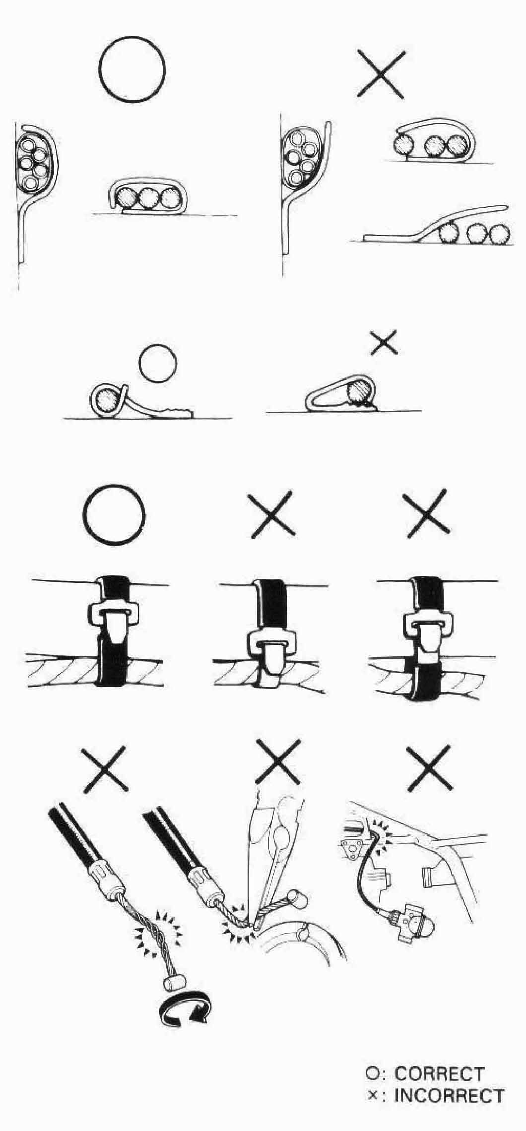
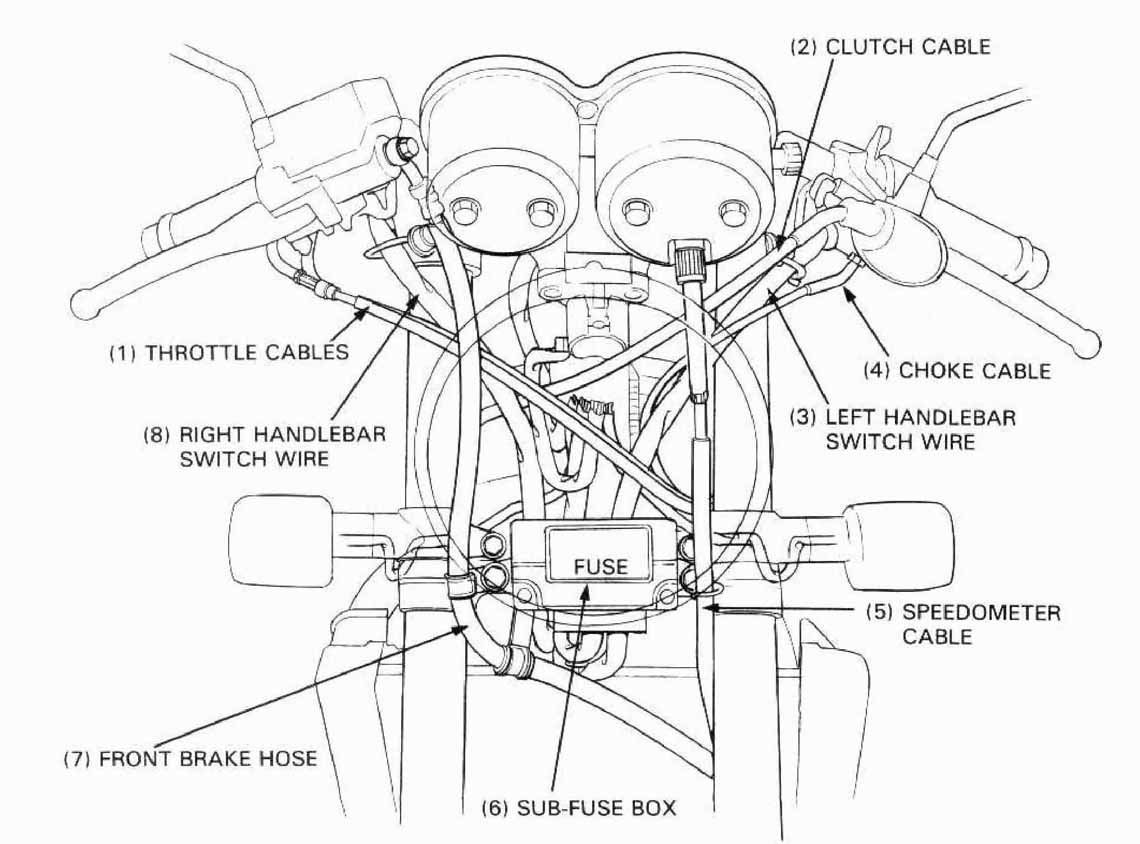
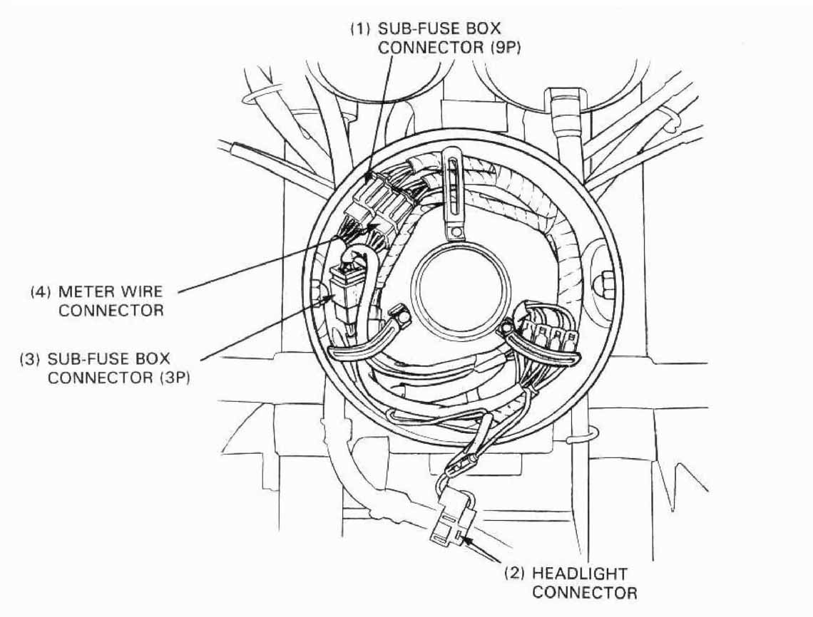
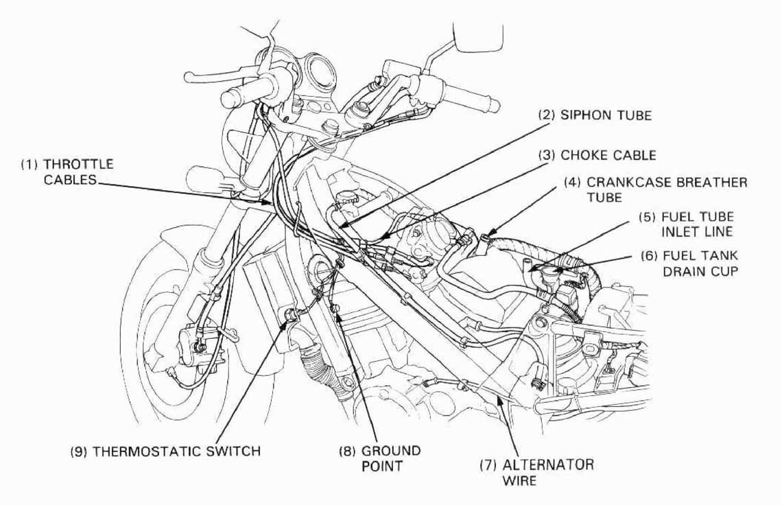
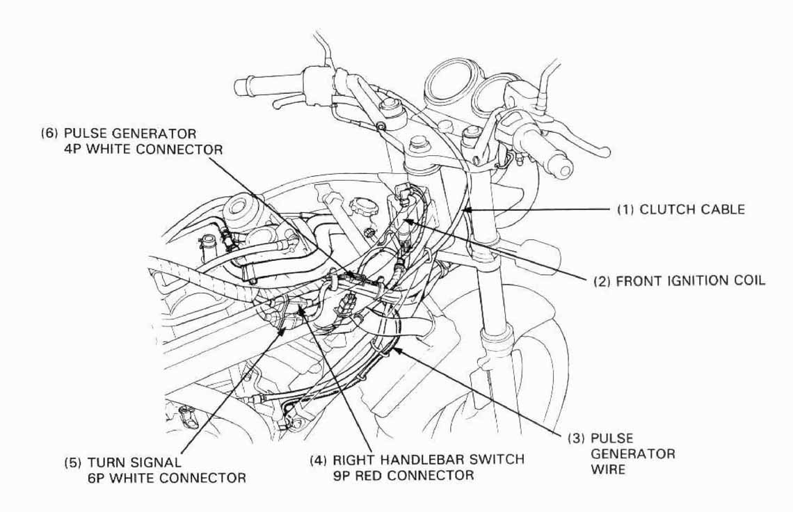
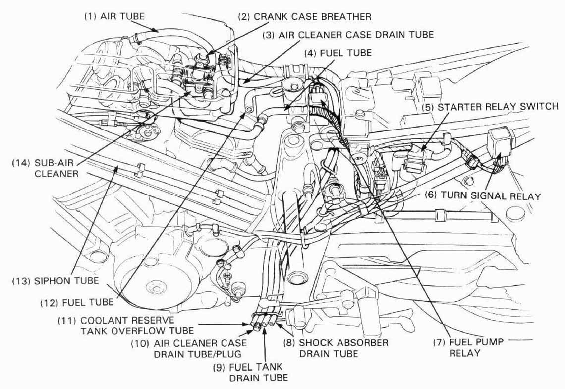
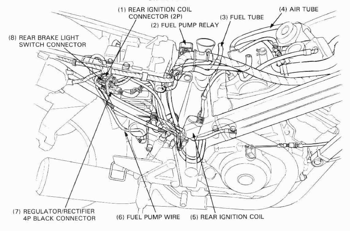
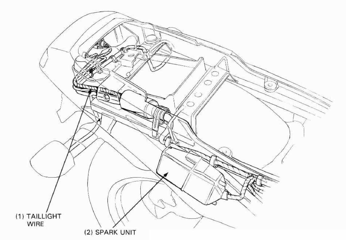
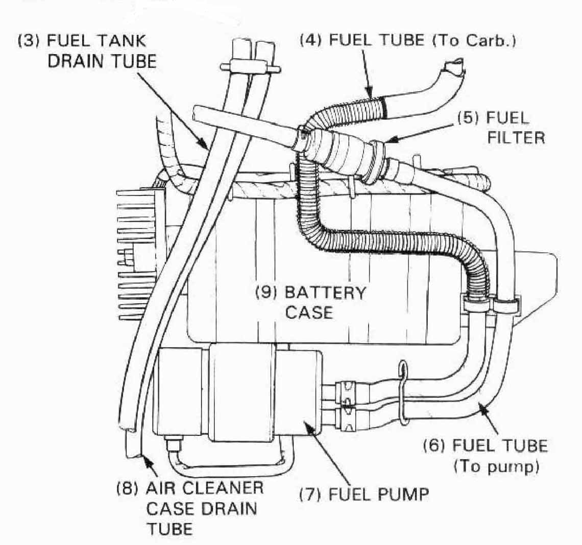
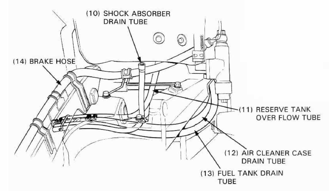
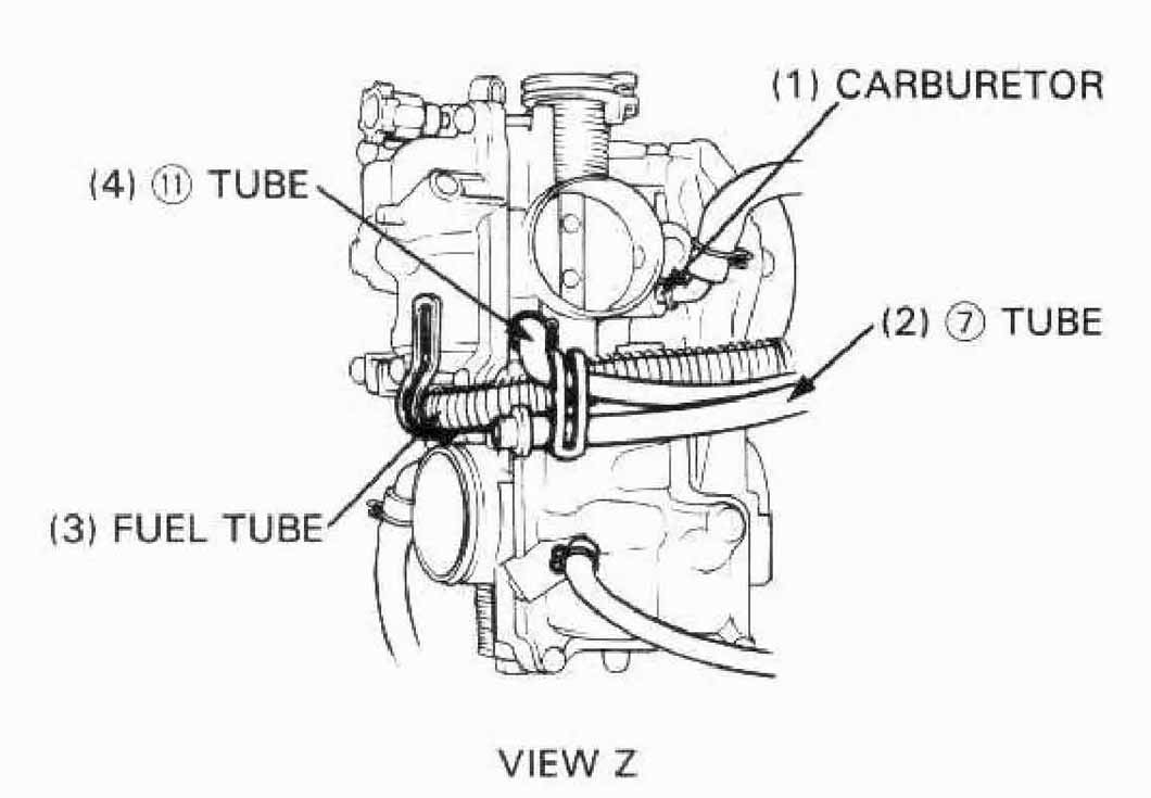
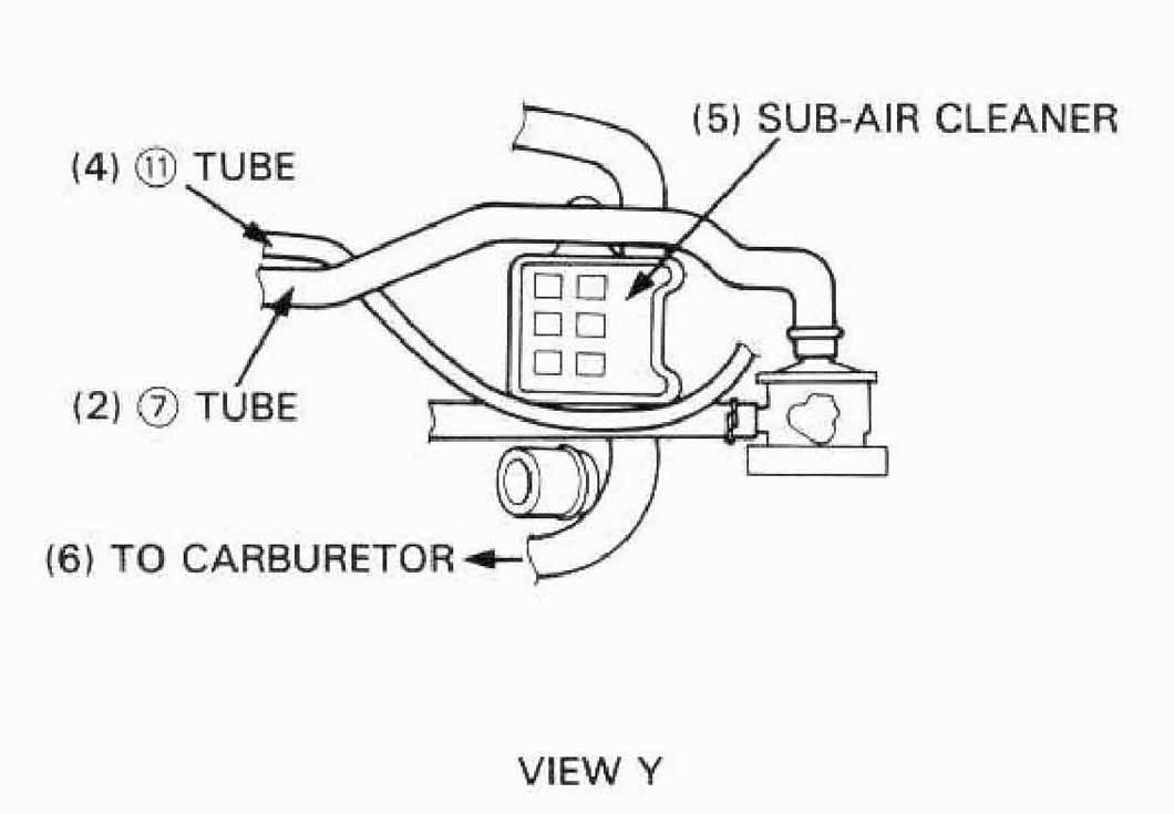
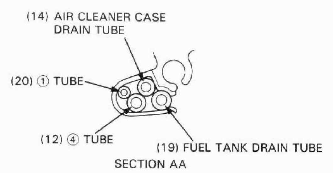
Note the following when routing cables and wire harnesses:
The U.S. Environmental Protection Agency and California Air Resources Board (CARB) require manufacturers to certify that their motorcycles comply with applicable exhaust emissions standards during ther useful life, when operated and maintained according to the instrutions provided, and the E.P.A. requires that motorcycles built after January 1, 1983 comply with applicable noise emissions standards for one year or 6,000 km (3,730 miles) after the time of sale to the ultimate purchaser, when operated and maintained according to the instructions provided. Compliance with the terms of the Distributor’s limited Warranty for Honda Motorcycle Emission Control Systems is necessary in order to keep the emissions system warranty in effect.
The combustion process produces carbon monoxide and hydrocarbons. Control of hydrocarbons is very important because, under certain conditions, they react to form photochemical smog when subjected to sunlight. Carbon monoxide does not react in the same way, but it is toxic.
Honda Motor Co., Ltd. utillizes lean carburetor settings as well as other systems, to reduce carbon monoxide and hydrocarbons.
Except for California:
The exhaust emission control system is composed of a lean carburetor
setting, and no adustments should be made except idle speed adjustment
with the stop screw. The exhaust emission control system is
separate from the crankcase emission control system.
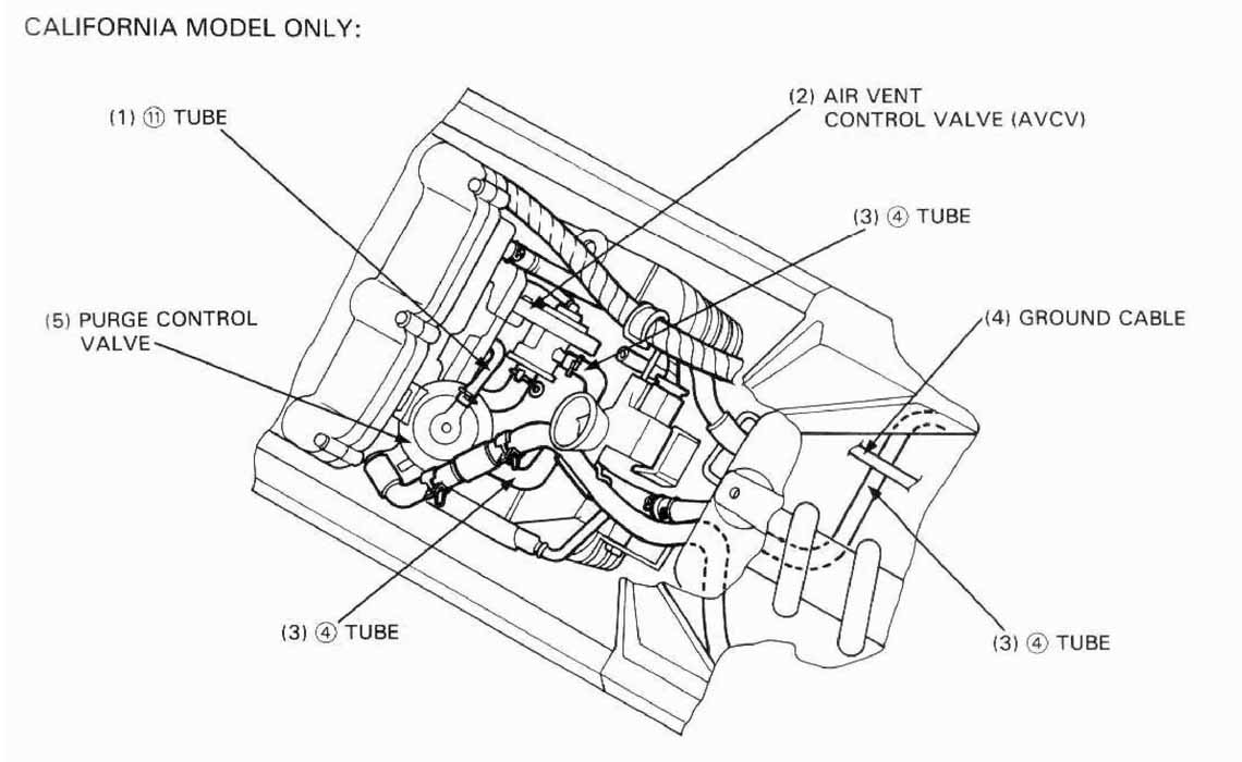
California only:
The exhaust emission control system consists of a secondary air suoply
system which introduces filtered air into the exhaust gasses in the
exhaust port. No adjustments to this system should be made,
although periodic inspection of the components is recommended.
The secondary air supply system helps improve emission performance.
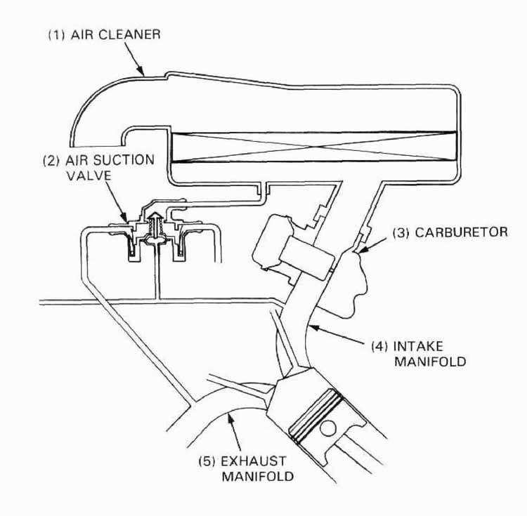
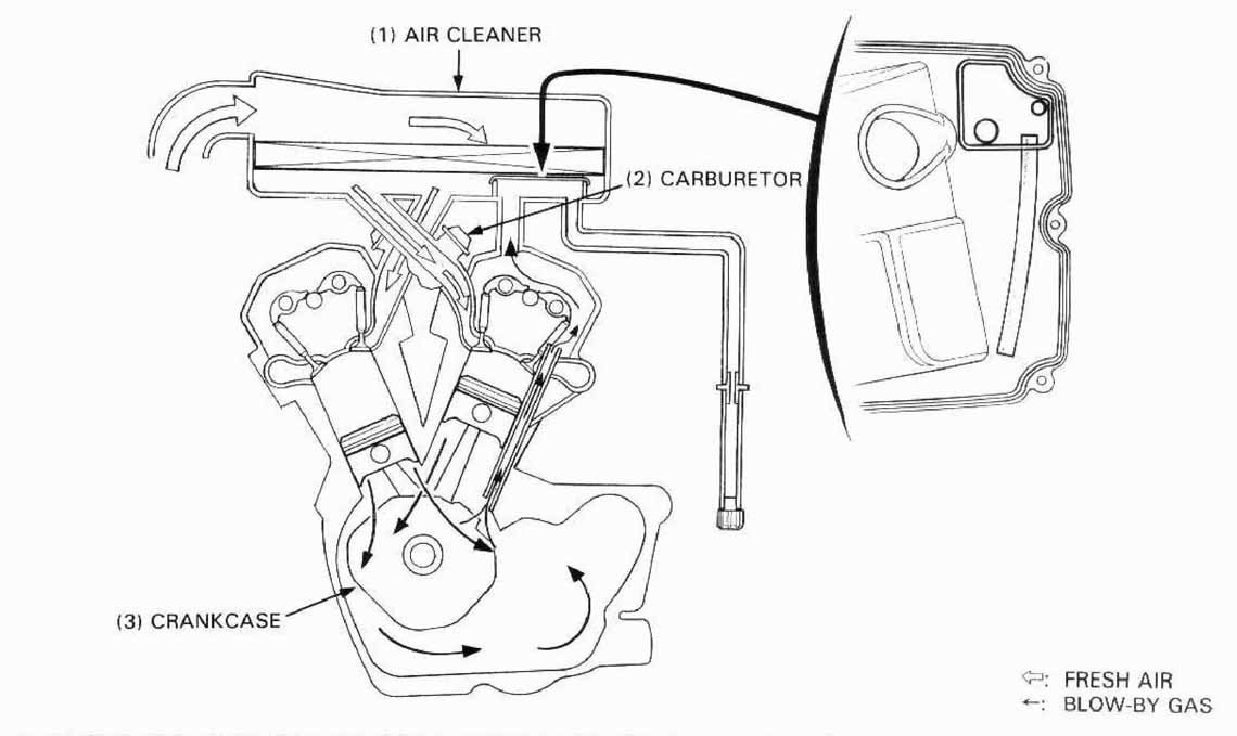
The engine is equipped with a closed crankcase system which routes crankcase emissions through the air cleaner into the combustion chamber.
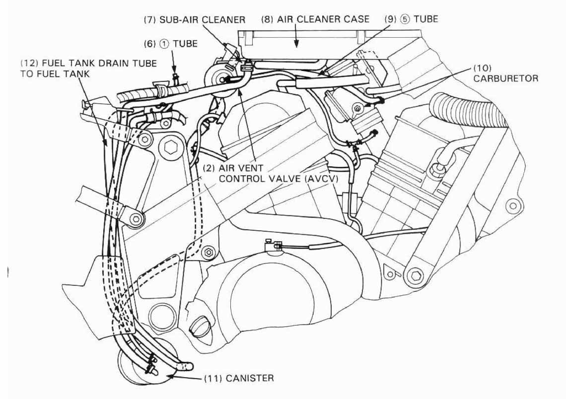
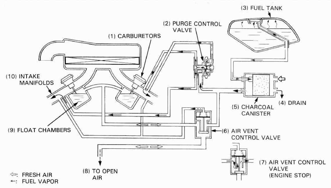
This model complies with California Air Resources Board evaporative emission requirements.
Fuel vapor from teh fuel tank and carburetor is directed into the charcoal canister wher it
is adsorbed and stored while teh engien is stopped. When the engine is running and
the purge control diaphragm valve is open, fuel vapor in the charcoal canister is drawn
into the engine through the carburetor.
TAMPERING WITH THE NOISE CONTROL SYSTEM IS PROHIBITED: Federal law prohibits the following acts or the causing thereof: (1) The removal or rendering inoperative by any person, other than for purposes of maintenance, repair, or replacement, of any device or element of design incorporated into any new vehicle for the purpose of noise control prior to its sale or delivery to the ultimate purchaser or while it is in use; or (2) the use of the vehicle after such device or element of design has been removed or rendered inoperative by any person.
AMONG THOSE ACTS PRESUMED TO CONSTITUTE THE TAMPERING ARE THE ACTS LISTED BELOW:
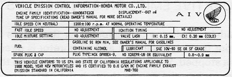
An Emission Control Information Label is located on the rear fender as shown. It contains basic tune-up specifications.
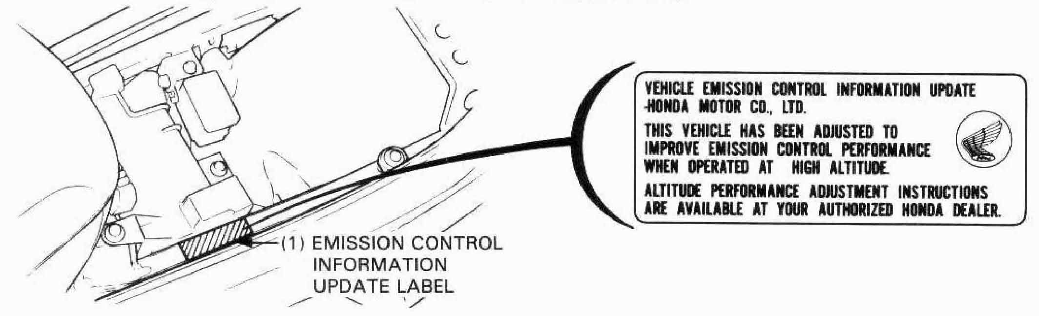
After making high altitude carburetor adjustment (Page 4-15),
attach an update label on the left sub-frame upper pipe.
Instructions for obtaining the update label are given in Service Letter No. 132.
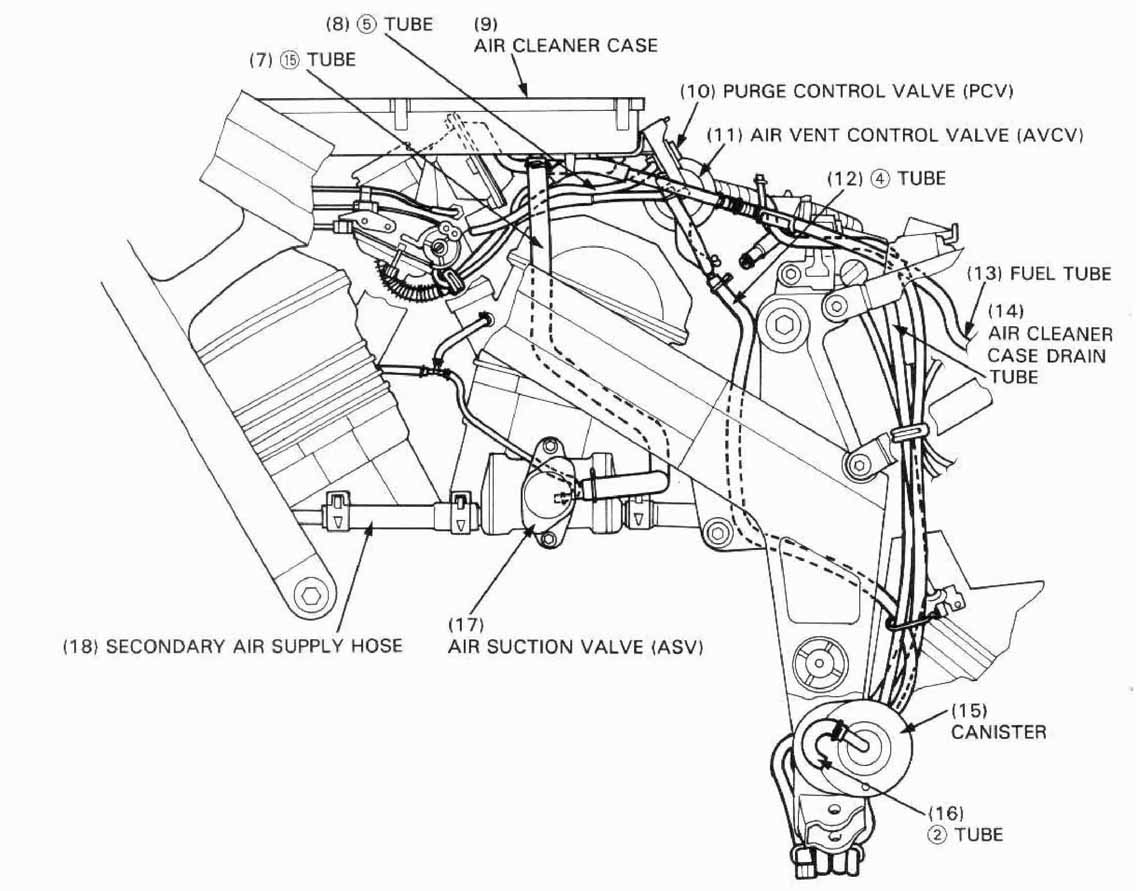
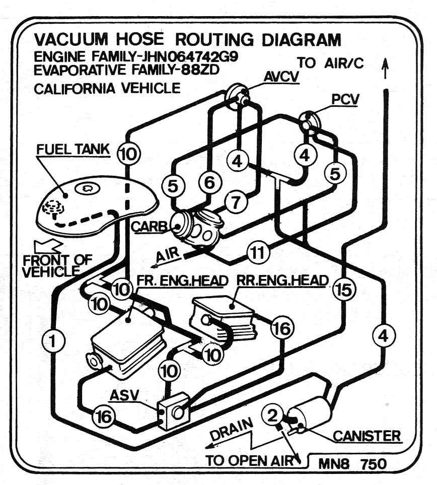
the Vacuum Hose Routing Diagram Label is on the air cleaner case cover. Route the vacuum hoses as shown on this label