really big verson
Hawkworks.net main page
Manual main index
| SERVICE INFORMATION | 4-1 |
| TROUBLESHOOTING | 4-2 |
| FUEL TANK | 4-3 |
| AIR CLEANER CASE | 4-4 |
| CARBURETOR REMOVAL | 4-5 |
| CARBURETOR DISASSEMBLY | 4-5 |
| PILOT SCREW REMOVAL | 4-7 |
| CARBURETOR ASSEMBLY | 4-9 |
| CARBURETOR SEPARATION/ASSEMBLY | 4-12 |
| CARBURETOR INSTALLATION | 4-14 |
| PILOT SCREW ADJUSTMENT | 4-14 |
| HIGH ALTITUDE ADJUSTMENT (U.S.A. only) | 4-15 |
| PURGE CONTROL VALVE INSPECTION (California model only) | 4-16 |
| AIR VENT CONTROL VALVE (California model only) | 4-17 |
| SECONDARY AIR SUPPLY SYSTEM (California model only) | 4-18 |
| ’88 | After ’88 | |||
|---|---|---|---|---|
| Item | 49 St. Model | California model | 49 St. Model | California model |
| Type | Constant Velocity dual carburetor | |||
| Throttle bore | 36.5 mm (1.4 in) | |||
| Identification No. | VDGKA | VDGLA | VDGKA | VDGLA |
| Float Level | 9.2 mm (0.36 in) | |||
| Main jet | Front: #138, Rear: #132 | |||
| Slow jet | #42 | |||
| Idle Speed | 1,200 +/- 100 rpm | |||
| Throttle grip free play | 2-6 mm (1/8-1/4 in) | |||
| Pilot screw initial opening | 2-1/8 | 2-1/2 | Front:1-1/2, Rear: 1 | 1-3/8 |
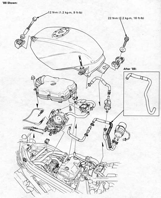
| Fuel tank mounting bolt | :Front | 12 N•m (1.2 kg-m, 9 ft-lb) |
| :Rear | 22 N•m (2.2 kg-m, 16 ft-lb) |
Special
| Vacuum/Pressure pump | A937X—041—XXXXX or |
| Pressure pump | ST—AH—255—MC7 (U.S.A. only) |
| Vacuum pump | ST—AH—260—MC7 (U.S.A. only) |
Common
| Float level gauge | 07401—0010000 |
Engine cranks but won’t start
Hard starting or stalling after starting
Rough idle
Afterburning during deceleration
Misfiring during acceleration
Backfiring
Poor performance (drivability) and poor fuel economy
Lean mixture
Rich mixture
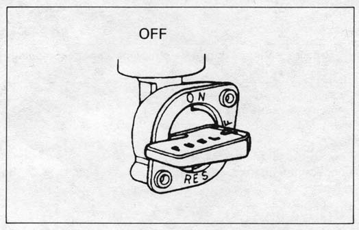
Remove the seat (page 13-25) and turn the fuel valve OFF.
Disconnect the fuel tube from the fuel tank.
All models:
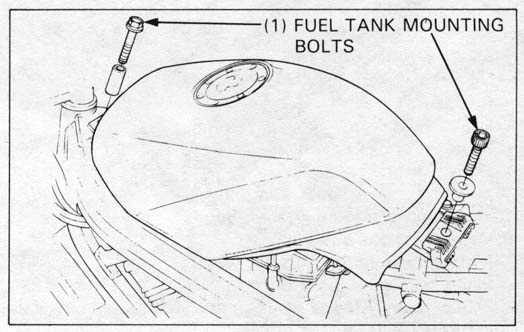
Remove the rear fuel tank mounting bolt first, then the front
bolt and remove the tank from the frame.
Check that fuel flows out of the fuel valve freely.
If flow is restricted, clean the fuel strainer.
All models:
Remove the fuel tank from the frame.
’88, After ’88:
Install the fuel tank in the frame.
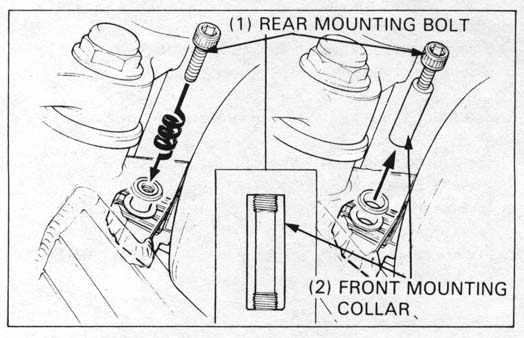
Install the front mounting collar and the bolt first, then the rear
mounting bolt.
| TORQUE: | ||
| Front: | 12 N•m (1.2 kg-m, 9 ft-lb) | |
| Rear: | 22N•m (2.2 kg-m, 16 ft-lb} | |
Connect the removed tubes securely.
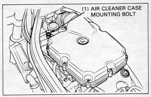
Remove the seat and fuel tank.
Remove the air cleaner case mounting bolt.
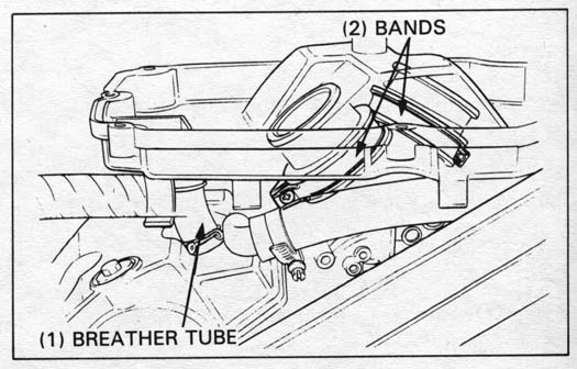
Loosen the air cleaner connecting tube band screws and disconnect
the crankcase breather and air cleaner case drain tube.
Remove the air cleaner case.
Install the air cleaner case in the reverse order of removal.
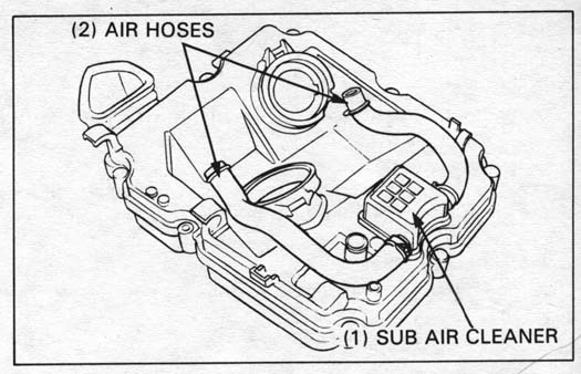
Remove the following:
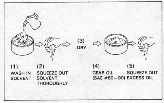
Wash the element in non-flammable or high flash point solvent,
squeeze out the solvent thoroughly, and allow the element
to dry.
Soak the element in gear oil (SAE #80 - 90) and squeeze out
the excess.
Reinstall the element and cover, and tighten the bolt.
Reconnect the air tubes from the carburetors.
Loosen the drain screws and drain the fuel into a container.
Remove the air cleaner case.
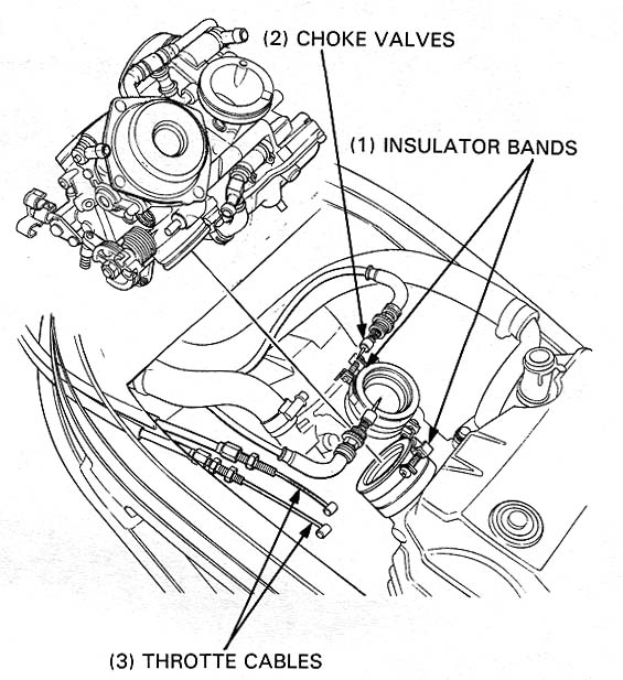
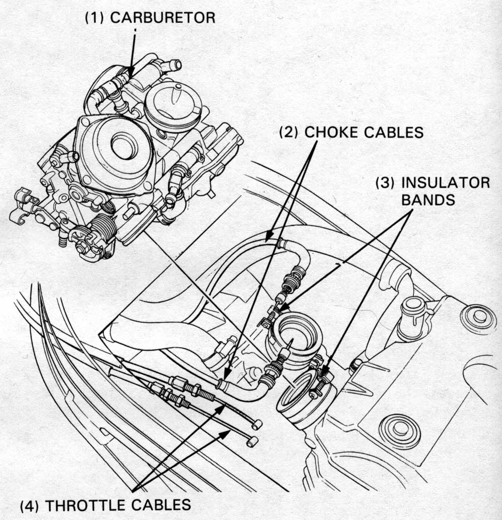
Disconnect the throttle cables from the carburetor.
Remove the choke valves from the carburetor and loosen the
carburetor insulator bands.
California model only:
Disconnect the purge control valve No. 5 tubes and air vent
control valve No. 6 and 11 tubes from the carburetor.
Pull the carburetors upward and away from the engine.
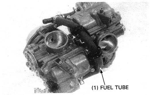
Remove the fuel tube from the carburetor.
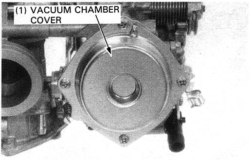
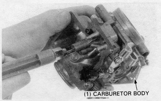
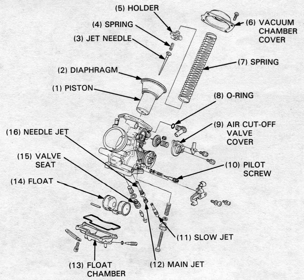
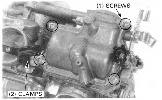
Remove the four screws and vacuum chamber cover.
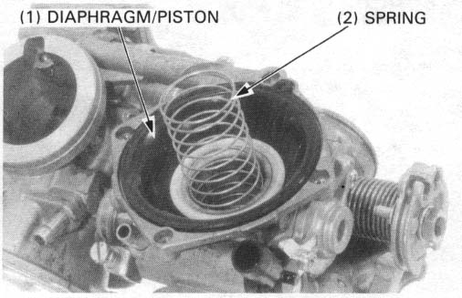
Remove the spring, piston/diaphragm.
Inspect the vacuum piston for wear, nicks, scratches or other damage.
Make sure the piston moves up and down freely in the chamber.
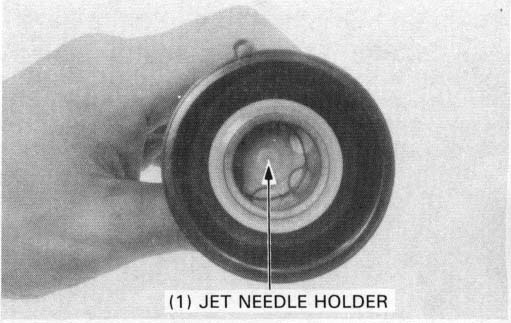
Push the jet needle holder in and turn it in 90 degrees counterclockwise.
Then remove the needle holder, spring, jet needle and from the
piston.
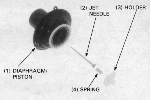
Inspect the needle for excessive wear at the tip, bending or
other damge.
Inspect the diaphragm for damage, fatigue or pin holes.
Inspect the vacuum piston for wear or damage.
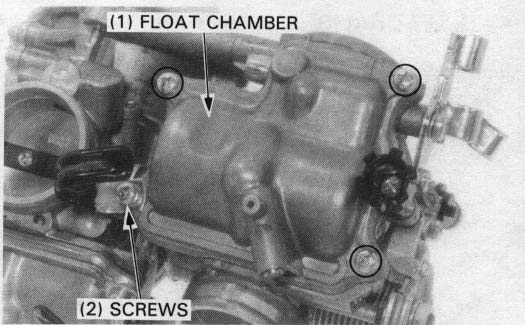
Remove the four screws and float chamber.
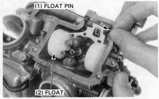
Remove the float pin, float and float valves.
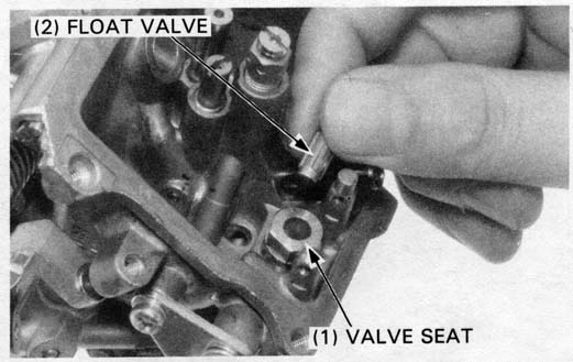
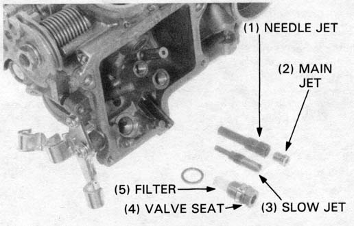
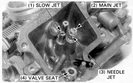
Remove the main jet, needle jet, slow jet and valve seat/filter.
Check each part for wear or damage.
Blow open all jets with compressed air.
Clean each jet with non-flammable or high flash point solvent.
Inspect the float valve seat and filter for grooves, nicks or deposits.
Clean the filter with low-pressure compressed air.
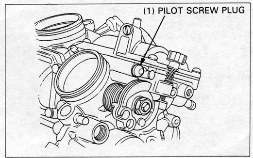
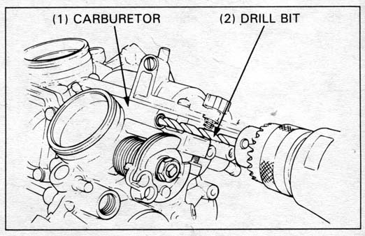
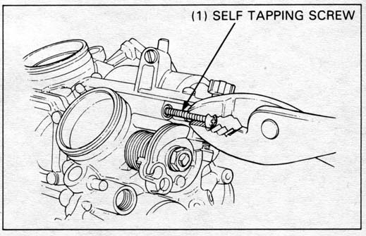
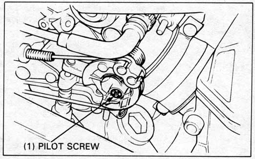
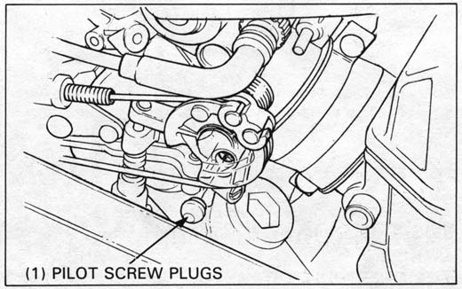
HINT: You don’t need a special screw to remove the cap. Any small sheet metal or wood screw will work as long as its width is enough to grab the hole and it isn’t so pointy as to hit the pilot screw. File the tip down to be extra careful.
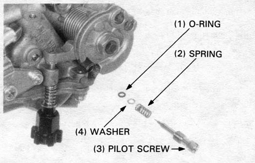
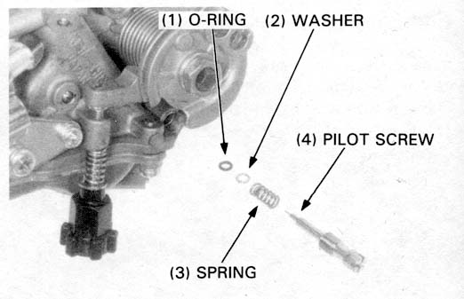
Turn each pilot screw in and carefully count the number of turns until it seats lightly. Make a note of this to use as a reference when reinstalling the pilot screws.
Remove the pilot screws and inspect them. Replace them if they are worn or damaged.
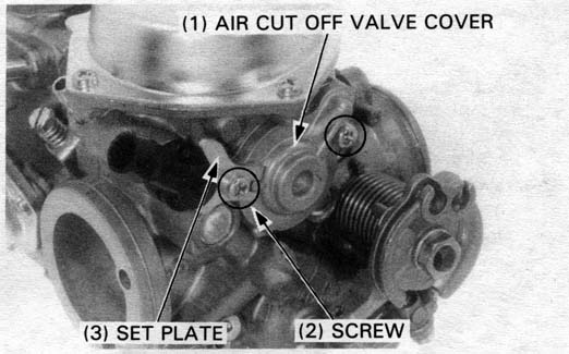
Remove the two screws, the set plate and the air cut off valve cover.
Separate the carburetors (page 4-12).
Remove the float valve, all jets, and the pilot screws.
Blow open all carburetor body openings with compressed air.
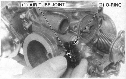
If the air tube joint was removed, install a new O-ring onto the air tube joint.
Install the air cut off valve cover with the joint set plate and tighten the screws securely.
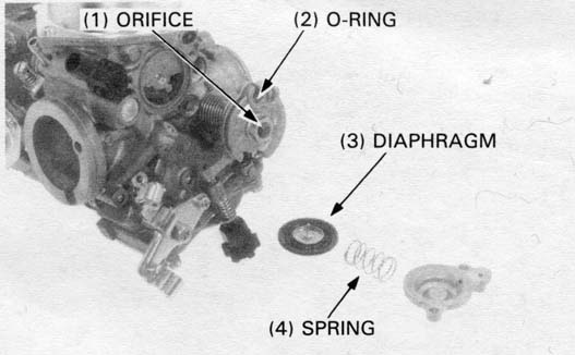
Be sure the diaphragm and spring are properly seated.
Install the pilot screws and return them to their original position as noted during removal.
Perform pilot screw adjustment if new pilot screws are installed (Page 4-14).
Install the pilot screw and turn it in until it seats lightly.
Turn the pilot screw out the number of turns recorded during removal.
Install the valve seat, slow jet, needle jet and main jet.
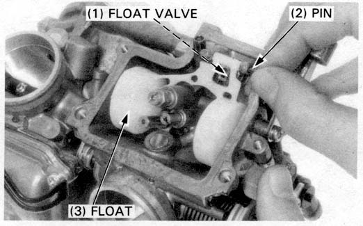
Install the float with float valve in the carburetor body, then install the float arm pin through the body and the float.
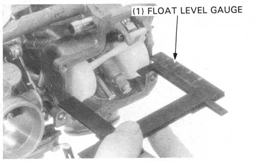
Measure the float level with the float tang just contacting the float valve.
FLOAT LEVEL: 9.2 mm (0.36 in)
Adjust the float level by carefully bending the tang.
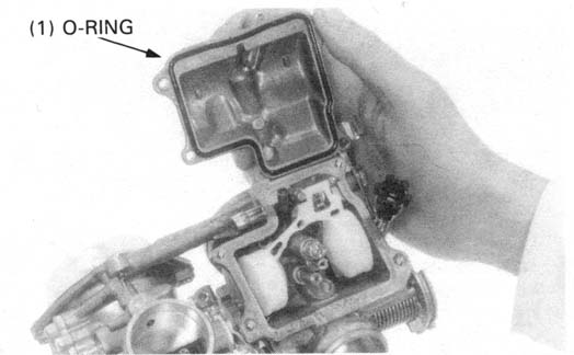
Install the new O-ring in the float chamber groove.
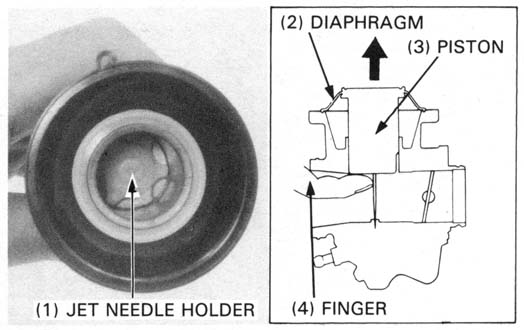
Install the washer, jet needle, spring and jet needle holder in
the vacuum piston.
Push the jet needle holder in and turn it in 90 degrees clockwise.
Hold the vacuum piston up to almost full open to avoid
pinching the diaphragm with the chamber cover.
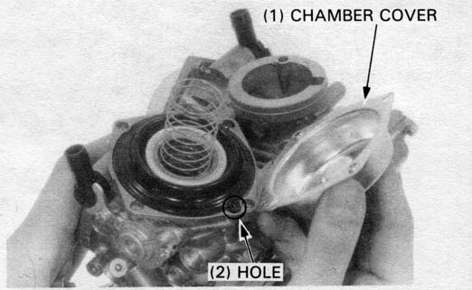
Install the vacuum piston, aligning the tab of the diaphragm with the groove of the carburetor.
Install the chamber cover with the spring, aligning the cover with the hole in the carburetor, and secure with at least two screws before releasing the vacuum piston.
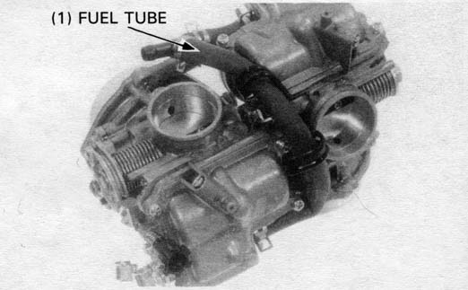
Install the fuel tubes as shown.
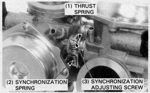
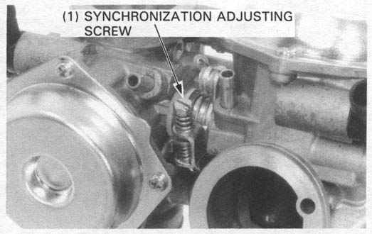
Loosen the synchronization adjusting screw.
Loosen the synchronization adjusting screw until there is no spring tension.
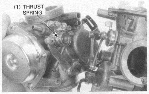
Install the thrust spring between the throttle links.
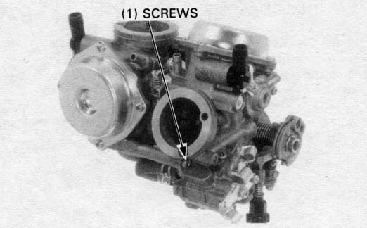
Secure the carburetors together with the two screws.
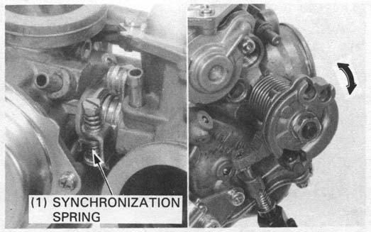
Install the synchronization spring and synchronization adjusting screw.
Inspect throttle operation as described below:
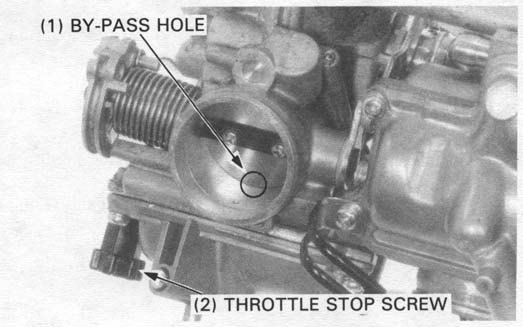
Turn the throttle stop screw to align the rear cylinder carburetor
throttle valve with the edge of the bypass hole.
Align the front cylinder carburetor throttle valve with the
bypass hole edge by turning the synchronization adjusting
screw.
Make sure the throttle returns smoothly to the fully closed position.
Install the carburetors onto the cylinder heads and tighten the insulator bands securely.
Install the following parts:
INITIAL OPENING:
| 49 St. model | California model | |
|---|---|---|
| ’88 | 2-1/8 turns out | 2-1/2 turns out |
| After ’88 | Front: 1-1/2 turns out Rear: 1 turns out | 1-3/8 turns out |
When the vehicle is to be operated continuously above 2,000m
(6,500 feet) the carburetors must be readjusted as follows
to improve driveability and decrease exhaust emissions.
Remove each pilot screw plug (page 4-7).
Warm up the engine to operating temperature. Stop and go
riding for 10 minutes is sufficient.
Turn each pilot screw clockwise 1/2 turn.
Adjust the idle speed to specification with the throttle stop
screw.
IDLE SPEED: 1,200 + 100 rpm
Drive new pilot screw plugs into the pilot screw bores
(page 4-7).
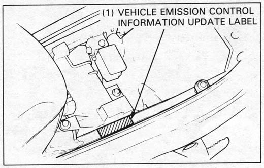
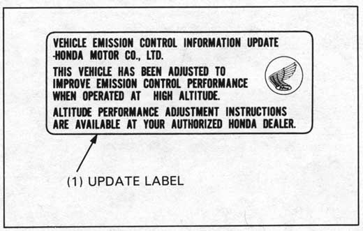
Attach a Vehicle Emission Control Information Update label on
the left sub-frame upper pipe as shown. See SL#132 for
information on obtaining the label.
When the vehicle is to be operated continuously below 1,500m (5,000 feet), turn each pilot screw counterclockwise 1/2 turn to its original position after removing each pilot screw plug and adjust the idle speed to specification (page 4-1). Drive new pilot screw plugs into the pilot screw bores (page 4-7). Be sure to do these adjustments at low altitude with the engine at normal operating temperature.
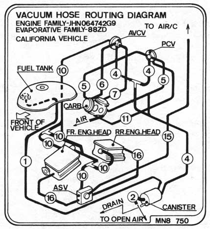
Check all fuel tank, Purge Control Valve (PCV), and charcoal canister hoses to be sure they are not kinked and are securely connected. Replace any hose that shows signs of damage or deterioration.
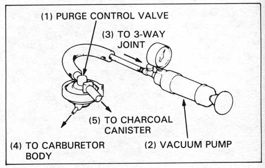
Disconnect the PCV hoses from their connections and remove the PCV from its mount. Refer to the routing label on the air cleaner case cover for hose connections.
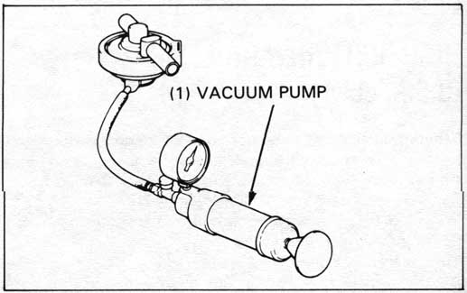
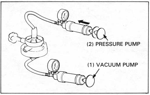
Connect a vacuum pump to the 8 mm (0.31 in.) I.D. hose No. 5 that goes to the 3-way joint. Apply the specified vacuum to the PCV.
SPECIFIED VACUUM: 250 mm (9.8 in) Hg
The specified vacuum should be maintained.
| TOOL: | |
| Vacuum/Pressure pump | A937X—041—XXXXX or |
| Vacuum pump | ST—AH—260—MC7 (U.S.A. only) |
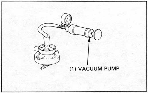
Remove the vacuum pump and connect it to the vacuum hose
No. 11 that goes to the left carburetor body.
Apply the specified vacuum to the PCV.
The specified vacuum should be maintained.
Replace the PCV if vacuum is not maintained
| TOOL: | |
| Vacuum/Pressure pump | A937X—041—XXXXX or |
| Vacuum pump | ST—AH—260—MC7 (U.S.A. only) |
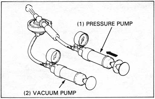
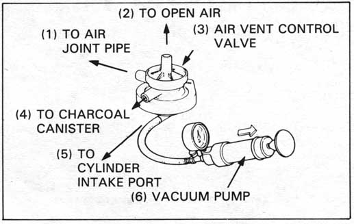
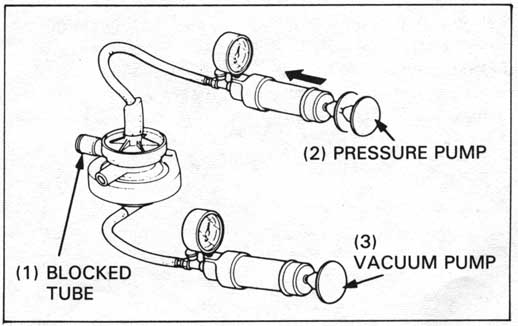
Connect a pressure pump to the 8 mm (0.31 in.) I.D. hose
No. 4 that goes to the charcoal canister. While applying
the specified vacuum to the PCV hose that goes to the
3-way joint pump air through the canister hose. Air
should flow through the PCV and out of the hose that goes
to the 3-way joint.
Replace the PCV if air does not flow out.
| TOOL: | |
| Vacuum/Pressure pump | A937X—041—XXXXX or |
| Vacuum pump | ST—AH—260—MC7 (U.S.A. only) |
| Pressure pump | ST—AH—255—MC7 (U.S.A. only) |
Remove the pumps, install the PCV on its mount, route and reconnect the hoses according to the routing label (page 4-18).
Disconnect the Air Vent Control Valve (AVCV) hoses
from their connections and remove the AVCV from its
mount. Refer to the routing label on the air cleaner
case cover for hose connections.
Connect a vacuum pump to the No. 10 hose that goes
to the right carburetor body.
Apply the specified vacuum to the AVCV.
SPECIFIED VACUUM: 250 mm (9.8 in) Hg
| TOOL: | |
| Vacuum/Pressure pump | A937X—041—XXXXX or |
| Vacuum pump | ST—AH—260—MC7 (U.S.A. only) |
The specified vacuum should be maintained. Replace the AVCV if vacuum is not maintained.
Connect the vacuum pump to the air vent port of the AVCV. Apply vacuum to the AVCV. The vacuum should hold steady. Replace the AVCV if vacuum leaks.
| TOOL: | |
| Vacuum/Pressure pump | A937X—041—XXXXX or |
| Vacuum pump | ST—AH—260—MC7 (U.S.A. only) |
Connect the vacuum pump to the No. 10 hose that goes to
the right carburetor body.
Connect the pressure pump to the air vent port of the
AVCV. While applying the vacuum to the AVCV No. 10
hose that goes to the right carburetor body, pump air
through the air vent port.
Air should flow through the AVCV and out of the hose
that goes to the carburetor air joint pipe.
| TOOL: | |
| Vacuum/Pressure pump | A937X—041—XXXXX or |
| Vacuum pump | ST—AH—260—MC7 (U.S.A. only) |
| Pressure pump | ST—AH—255—MC7 (U.S.A. only) |
Plug the hose that goes to the carburetor air joint pipe.
While applying vacuum to the AVCV No. 10 hose that goes to
the 3-way joint, apply air pressure. It should hold steady.
Replace the AVCV if pressure is not retained.
Remove the pumps, install the AVCV on its mount, route
and reconnect the hoses according to the routing label.
| TOOL: | |
| Vacuum/Pressure pump | A937X—041—XXXXX or |
| Vacuum pump | ST—AH—260—MC7 (U.S.A. only) |
| Pressure pump | ST—AH—255—MC7 (U.S.A. only) |
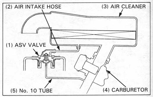
Check that the secondary air intake ports are clean and free of carbon deposits.
Check the secondary air intake hose for clogging, deterioration
or damage and replace if necessary.
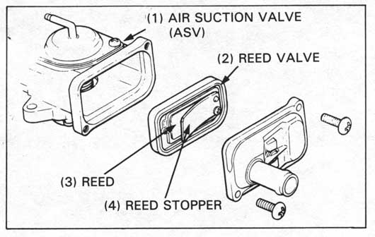
Check the reed valves in the air suction valve (ASV) if
the intake hose or supply hose is damaged by exhaust gas.
Disconnect the vacuum tube (No. 10) from the ASV and install
a plug in the vacuum tube to keep air from entering.
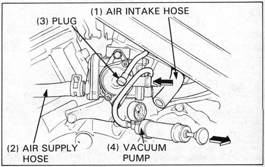
Connect the vacuum pump to the ASV.
| TOOL: | |
| Vacuum/Pressure pump | A937X—041—XXXXX or |
| Vacuum pump | ST—AH—260—MC7 (U.S.A. only) |
Start the engine and open the throttle slightly to be
certain that air is sucked in through the intake hose.
If air is not drawn in, check the air supply hoses and
vacuum tube for clogging.
With the engine running, gradually apply vacuum to the ASV.
Check that the air intake hose stops drawing air, and that
the vacuum does not bleed off.
SPECIFIED VACUUM:
300 - 370 mm (1 1.8 - 14.6 in) Hg
If air is still drawn in, or if the specified vacuum is not
maintained, install a new ASV.
If afterburn occurs on deceleration, even when the secondary
air supply system is normal, check the air cut-off valve for
correct vacuum operation.
Disconnect the air supply hoses from the reed valve covers of the ASV.
Disconnect the vacuum tube and air intake hose from the ASV.
Remove the ASV mounting bolts and ASV.
Remove the two screws, the reed valve cover and the reed valve from the ASV.
Check the reed valve for damage or fatigue, and replace if necessary.
Install a new reed valve if the seat rubber is cracked or damaged, or if there is clearance between the reed valve and seat.
Assemble and install the ASV in the reverse order of disassembly/removal.