
really big verson
Hawkworks.net main page
Manual main index
| SERVICE INFORMATION | 12-1 |
| TROUBLESHOOTING | 12-2 |
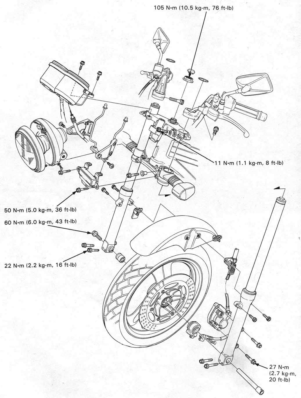
| HANDLEBARS | 12-3 |
| FRONT WHEEL | 12-7 |
| FORK | 12-12 |
| HEADLIGHT BRACKET | 12-19 |
| STEERING STEM | 12-20 |
Unit: mm (in)
| ITEM | STANDARD | SERVICE LIMIT | |
|---|---|---|---|
| Axle runout | — | 0.2 (0.01) | |
| Front wheel rim runout | Radial | — | 2.0 (0.08) |
| Axial | — | 2.0 (0.08) | |
| Fork spring free length | — | 336.4 (13.2) | |
| Fork tube runout | — | 0.2 (0.01) | |
| Fork fluid capacity * | ’88: | 497cc (16.8 US oz, 17.4 imp oz) | — |
| After ’88: | 502cc (16.9 US oz, 17.6 Imp oz) | ||
| Fork fluid level * | ’88: | 133 (5.2) | — |
| After ’88: | 128 (5.0) | ||
| Steering bearing preload | 1.0-1.5 kg (2.2-3.3 lb) | — | |
* Info: Fork fluid capacity and level will be a lot lower
if you have aftermarket springs.
e.g.: RaceTech specifies 160mm oil height — about 30mm / 3 oz less than factory spec.
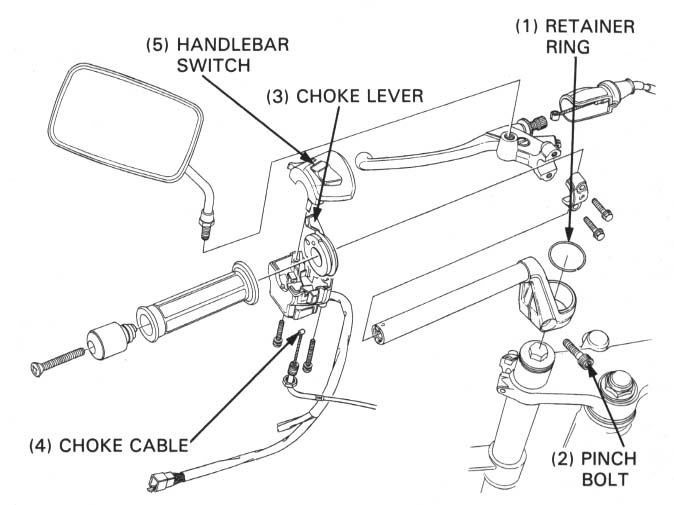
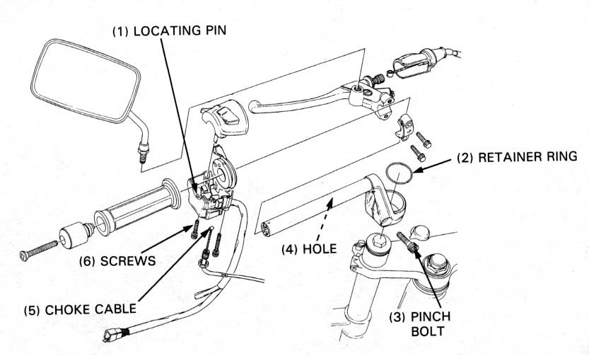
Disconnect the choke cable and remove the left handlebar switch from the choke lever.
Remove the left handlebar retainer ring and loosen the left handlebar pinch bolt.
Remove the left handlebar from the fork tube.
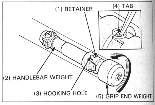
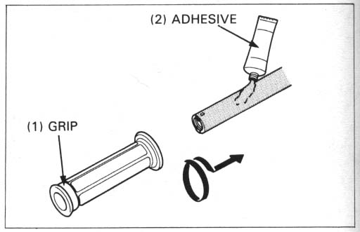
Remove the grip from the handlebar.
Straighten the weight retainer tab with a screwdriver or center punch.
Remove the handlebar weight by turning the grip end weight.
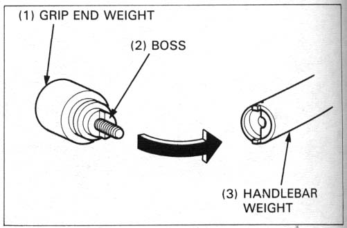
Remove the grip end weight by removing the mouinting screw from the
handlebar weight.
Discard the used retainer
Install the new retainer onto the handlebar weight.
Install the grip end weight onto the handlebar weight aligning the boss with slot.
Clean and apply a locking agent to the mounting screw threads and tighten it securely.
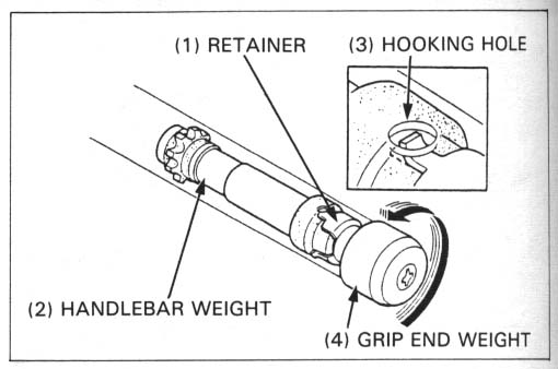
Insert the handlebar weight assembly onto the handlebar.
Hooking the retainer tab to the hooking hole securely.
Install the grip onto the handlebar.
TORQUE: 27 N•m (2.7 kg-m, 20 ft-lb, 240 in-lb)
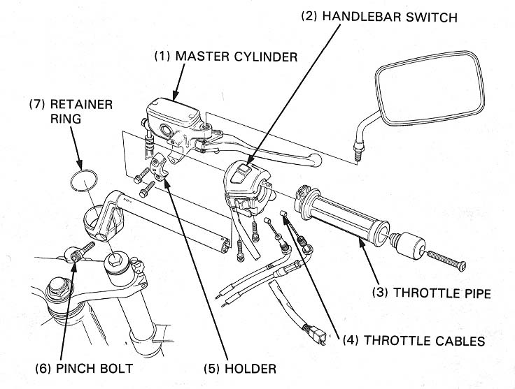
Align the locating pin on the right handlebar switch with the hole in the handlebar.
Apply clean grease to the throttle cables and apply clean oil to the throttle pipe sliding surface and connect the throttle cables to the throttle pipe.
Slide the throttle pipe onto the handlebar.
Install the right grip end-weight and tighten the screw.
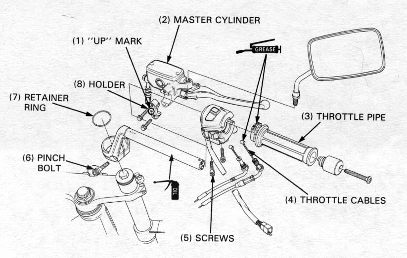
Place the front brake master cylinder on the handlebar adn install the master cylinder holder with the "UP" mark facing up.
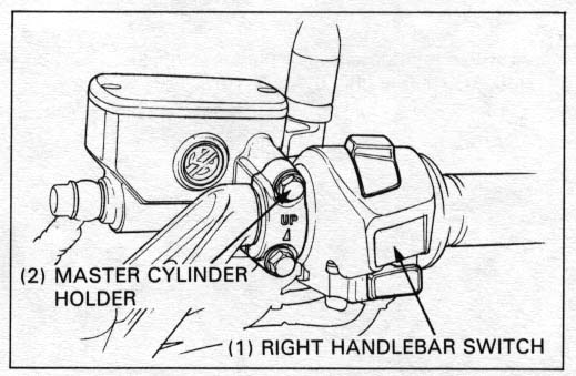
Align the end of the holder with the punch mark on the handlebar. Tightent the upper holder bolt first, then tighten the lower bolt.
TORQUE: 12 N•m (1.2 kg-m, 9 ft-lb, 108 in-lb)
Connect the front brake switch wire.
Install the right handlebar switch mounting screws.
tighten the front screw first, then tighten the rear screw.
Install the throttle cables to the carburetor and adjust the
throttle grip free play (page 3-4).
Install the right rear-view mirror intohe master cylinder holder.
Install the left handlebar onto the fork tube in the same manner
as the right handlebar.
Connect the choke cable to the choke lever.
Install the left handlebar switch by aligning the locating pin
with the hole in the handlebar.
Tighten the front screw first, then tighten the rear screw.
Install the right rear view mirror in the holder.
Secure the wires with wire bands.
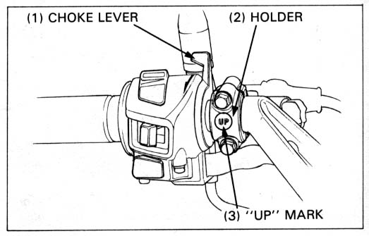
Install the clutch lever and holder with the "UP" mark facing up.
Align the end of the holder with the punch mark on the handlebar
and tighten the upper bolts first then tighten the lower bolt.
TORQUE: 12 N•m (1.2 kg-m, 9 ft-lb, 108 in-lb)
Adjust the following:
Raise the front wheel off the ground.
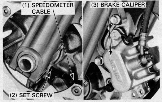
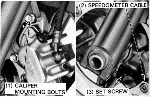
Disconnect the speedometer cable from the speedometer gear
box by removing the cable set screw.
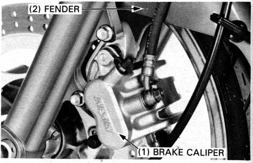
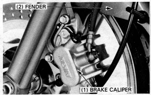
Remove the brake caliper mounting bolts and brake caliper.

Loosen the right and left front axle pinch bolts, and remove the axle bolt.
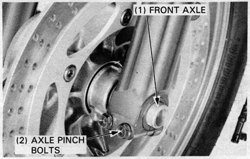
Remove the axle and the front wheel.
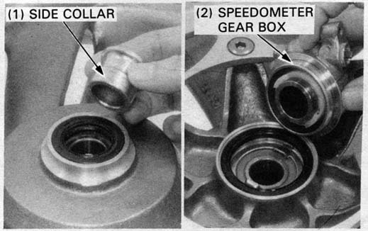
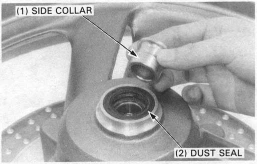
Remove the side collar from the right side and remove the speedometer gear box from the left side.
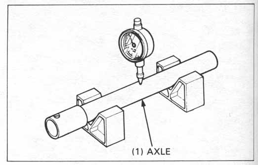
Set the axle in V blocks and measure the runout.
SERVICE LIMIT: 0.2 mm (0.01 in)
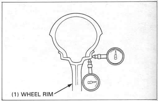
SERVICE LIMITS:
RADIAL RUNOUT: 2.0 mm (0.08 in)
AXIAL RUNOUT: 2.0 mm (0.08 in)
SERVICE LIMITS:
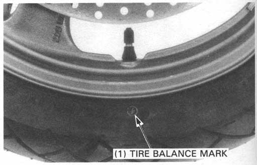
Wheel Balance
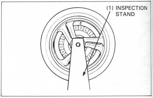
Mount the wheel, tire and brake disc assembly in an inspection
stand.
Spin the wheel, allow it to stop, and mark the lowest
(heaviest) part of the wheel with chalk.
Do this two or three times to verify the heaviest area. If the
wheel is balanced, it will not stop consistently in the same po
sition.
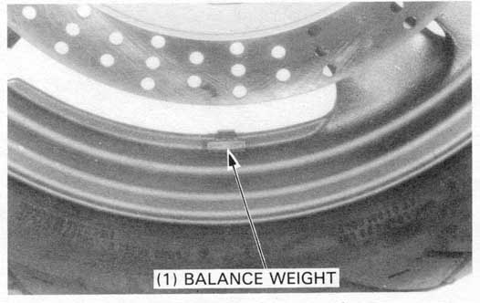
To balance the wheel, install wheel weights on the highest side of the rim, the side opposite the chalk marks. Add just enough weight so the wheel will no longer stop in the same position when it’s spun. Do not add more than 60 grams to the front wheel.
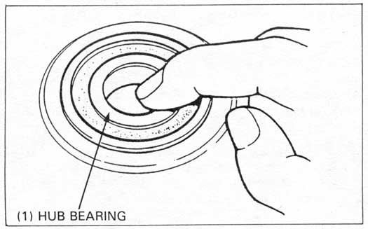
Wheel bearing
Turn the inner race of each bearing with your finger. The
bearings should turn smoothly and quietly. Also check that the
bearing outer race fits tightly in the hub.
Remove and discard the bearings if the races do not turn smoothly, quietly, or if they fit loosely in the hub.
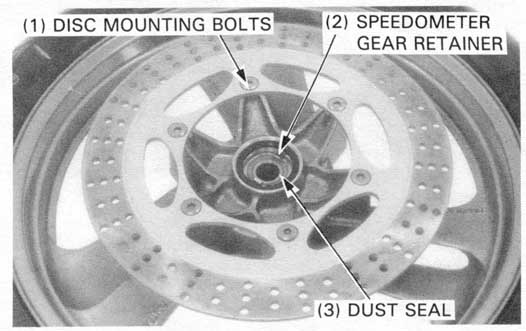
Remove the brake disc mounting bolts and discs.
Remove the dust seal from both sides.
Remove the speedometer gear retainer.
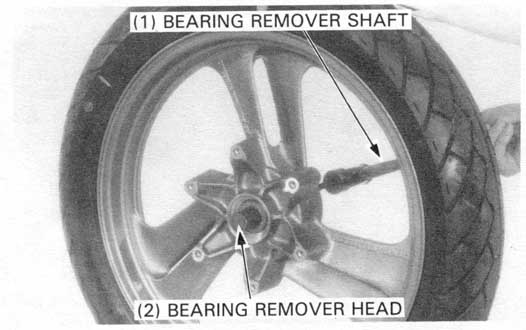
Install the bearing remover head into the bearing.
From the opposite side install the bearing remover
shaft and drive the bearing out of the wheel.
| TOOLS: | |
| Bearing remover shaft | 07746—0050100 |
| Bearing remover head, 20 mm | 07746—0050600 |
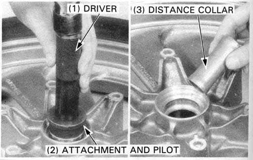
Drive a new right bearing into the wheel until it is fully seated first.
| TOOLS: | |
| Driver | 07749—0010000 |
| Attachment, 42 x 47 mm | 07746—0010300 |
| Pilot, 20 mm | 07746—0040500 |
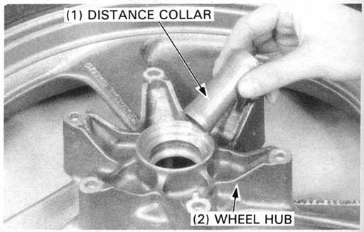
Install the distance collar into the wheel hub.
Drive a new left bearing into the wheel until it is fully seated.
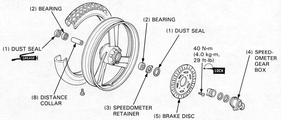
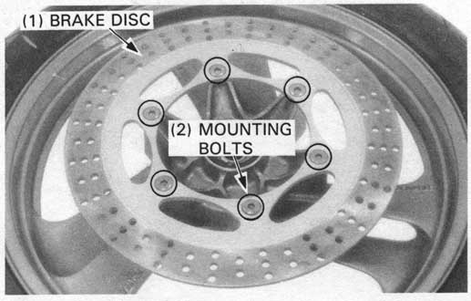
Install the brake disc onto the wheel hub with the minimum
thickness marking (MIN TH 4.0 mm) facing out.
Clean and apply locking agent to the mounting bolt threads.
Tighten the bolts to the specified torque in a crisscross pattern
in 2 or 3 steps.
TORQUE: 40 N•m (4.0 kg-m, 29 ft-lb)
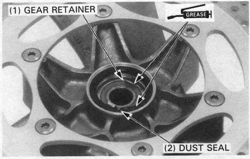
Coat the speedometer gear retainer with clean grease and install
the retainer into the wheel hub, aligning the tangs with the
slots in the hub.
Apply clean grease to the dust seal lip and install the dust
seal over the gear retainer.
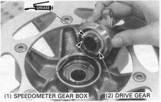
Fill the speedometer gear box with clean grease and install the drive gear.
Install the speedometer gear box into the wheel hub.
Position the wheel between the fork legs.
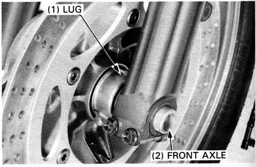
Insert the axle from the leftside, through the
left fork leg and wheel hub.
Position the tang on the speedometer gear box against the back of the lug on the left fork leg.
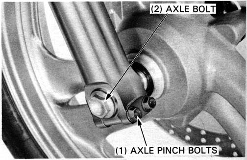
Insert and tighten the axle bolt.
TORQUE: 60 N•m(6.0kg-m, 43 ft-lb)
Tighten the axle pinch bolts.
TORQUE: 22 N•m (2.2 kg-m, 16 ft-lb, 192 in-lb)
Install the brake caliper with the caliper bracket.
Install the caliper mounting bolts and tighten the bolts.
TORQUE: 27 N•m (2.7 kg-m, 20 ft-lb, 240 in-lb)
Connect the speedomater cable with the set screw.
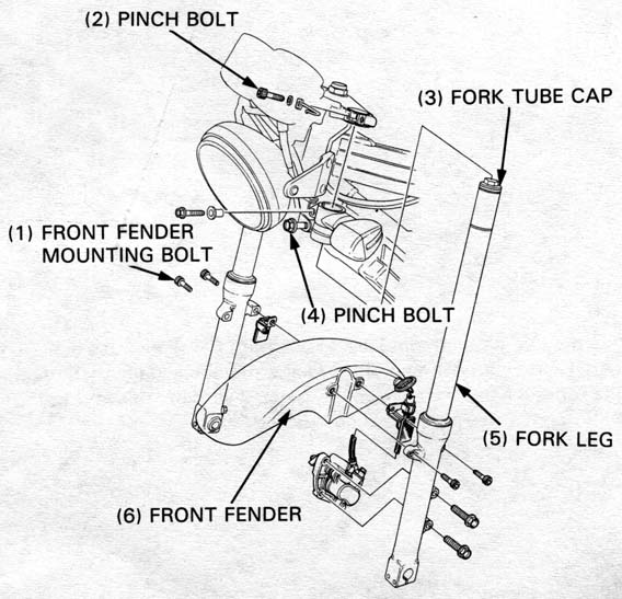
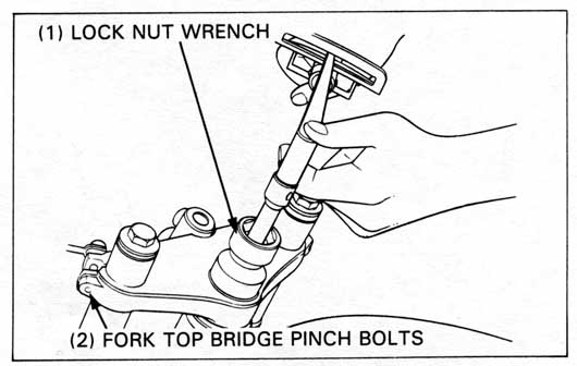
Loosen the fork top bridge pinch bolts.
If the fork legs will be disassembled, loosen the fork tube caps
but do not remove them yet.
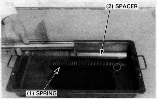
Remove the fork tube cap and the spring.
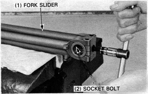
Hold the fork slider in a vise with soft jaws or use a shop towel.
Remove the socket bolt with a hex wrench.
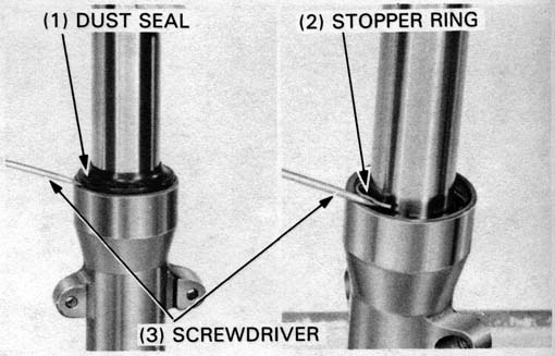
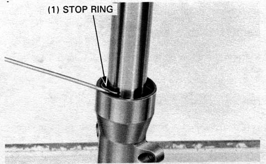
Remove the dust seal and the stop ring with a screwdriver.
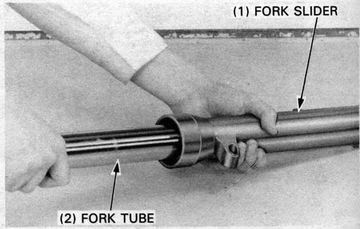
Pull the fork tube out until resistance from the slider bushing is felt. Then move it in and out, tapping the bushing lightly until the fork tube separates from the slider. The slider bushing will be forced out by the fork tube bushing.
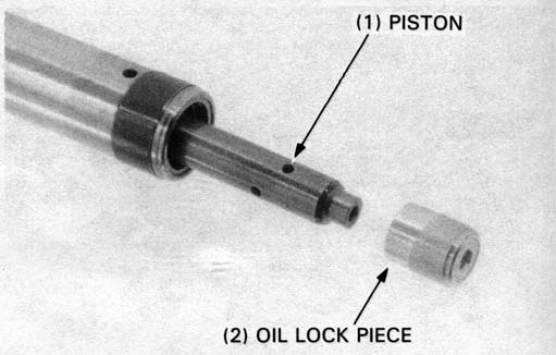
Remove the oil lock piece from the piston.
Remove the piston and rebound spring from the fork tube.
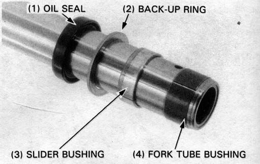
Remove the oil seal, back-up ring and slider bushing from the fork tube.
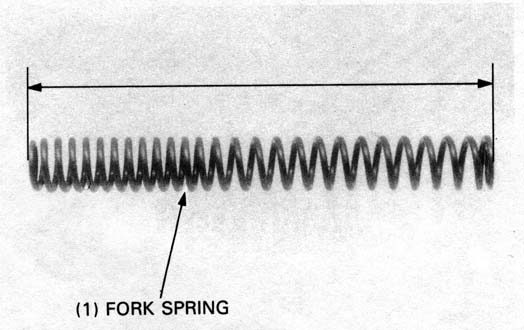
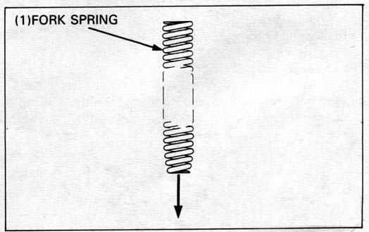
Fork spring
Measure the fork spring free length.
SERVICE LIMIT: 336.4 mm (13.2 in)
Replace the spring if it is shorter than the service limit.
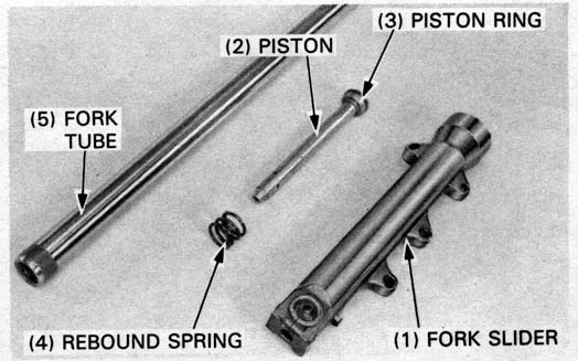
Fork tube/slider/piston
Check the fork tube, fork slider and piston for score marks and
excessive or abnormal wear.
Replace any components which are worn or damaged.
Check the fork piston ring for wear or damage.
Check the rebound spring for fatigue or damage.
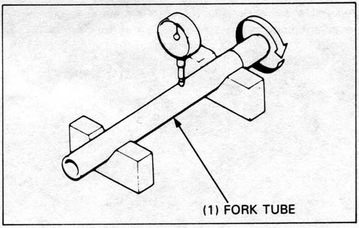
Set the fork tube in V blocks and read the runout.
Use 1/2 the total indicator reading to determine the actual runout.
SERVICE LIMIT: 0.20 mm (0.008 in)
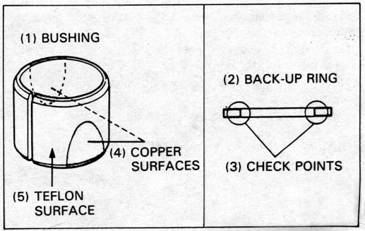
Visually inspect the slider and fork tube bushings.
Replace the bushings if there is excessive scoring or
scratching, or if the teflon is worn so that the copper
surface appears on more than 3/4 of the entire surface.
Check the back-up ring; replace it if there is any distortion at the points shown.
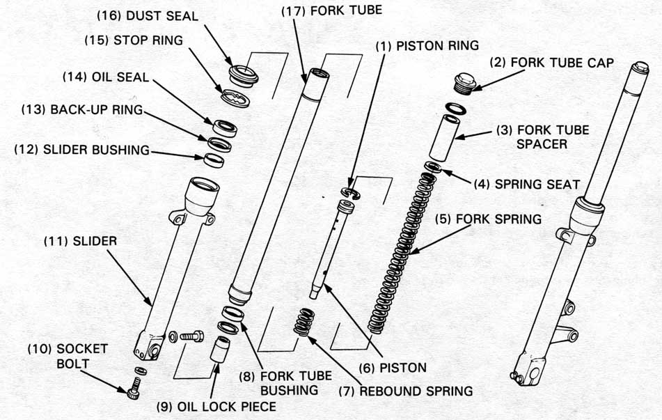
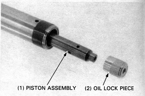
Assemble the rebound spring onto the piston.
Insert the piston assembly into the fork tube.
Place the oil lock piece on the end of the piston and
insert the fork tube assembly into the slider.
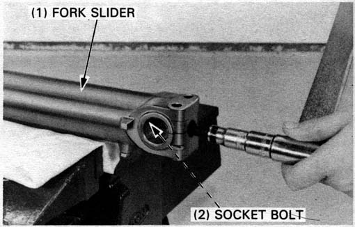
Place the fork slider in a vise with soft jaws or use a shop towel to avoid damaging the slider.
Clean and apply a locking agent to the socket bolt threads and screw the bolt into the piston.
Temporarily install the fork spring and cap to tighten the socket bolt.
Tighten the bolt with a 6 mm hex wrench.
TORQUE: 17 N•m (1.7 kg-m, 12 ft-lb, 144 in-lb)
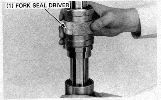
Place the slider bushing over the fork tube and rest it on the slider.
Drive the bushing into place with the seal driver.
Coat a new oil seal with ATF or equivalent and install it with the seal markings facing up. Drive the seal in with the seal driver.
| TOOLS: | |
| Fork seal driver | 07947—KA50100 |
| — driver attachment | 07947—KF00100 |
Install the new dust seal onto the fork slider.
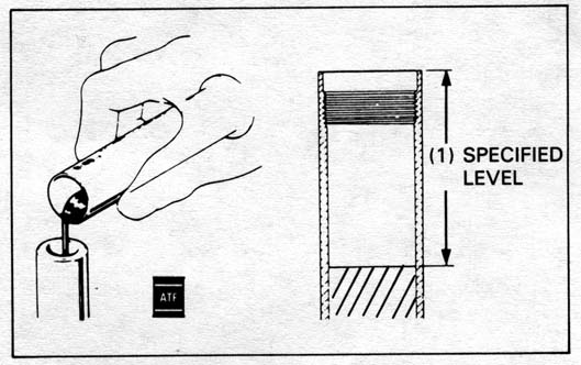
Compress the fork tube and pour in the recommended fork oil to the specified level.
RECOMMENDED FORK OIL: ATF or EQUIVALENT
| SPECIFIED LEVEL: | ’88: | 133 mm (5.2 in) |
| After ’88: | 128mm (5.0 in) | |
| CAPACITY: | ’88: | 497 cc (16.8 US oz, 17.4 Imp oz) |
| After ’88: | 502 cc (16.9 US oz, 17.6 Imp oz) | |
Gently install the fork spring in the fork tube then install the spring seat and spacer.
Loosely install the fork tube cap with a new O-ring.
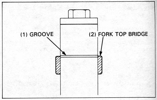
Install the fork legs into the steering stem and fork top bridge and align the groove of the fork tube with the top of the bridge.
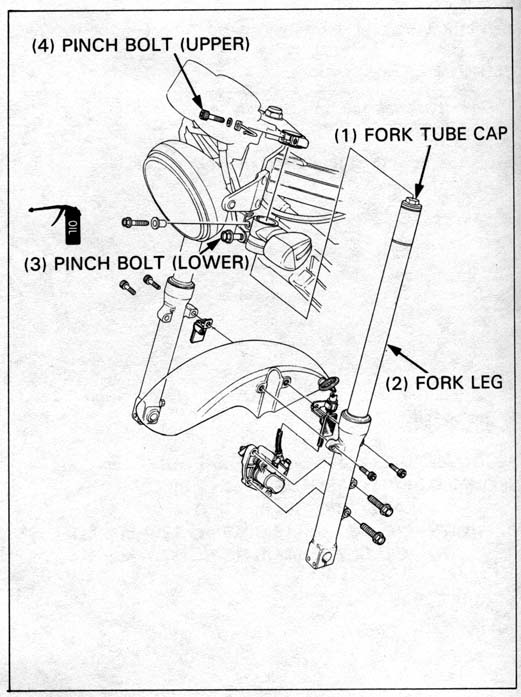
Apply oil to the lower pinch bolt threads and tighten the bolt.
TORQUE: 50 N•m (5.0 kg-m, 36 ft-lb)
Screw in the upper pinch bolt but do not tighten it.
First, tighten the fork tube cap.
TORQUE: 23 N•m (2.3 kg-m, 17 ft-lb 204 in-lb)
Next, tighten the top pinch bolt to avoid damage the fork cap threads.
TORQUE: 11 N•m (1.1 kg-m, 8ft-lb, 96 in-lb)
install the following:
Remove the following:
Disconnect the headlight wire connector.
Remove the headlight case mounting bolts and headlight case from the bracket.
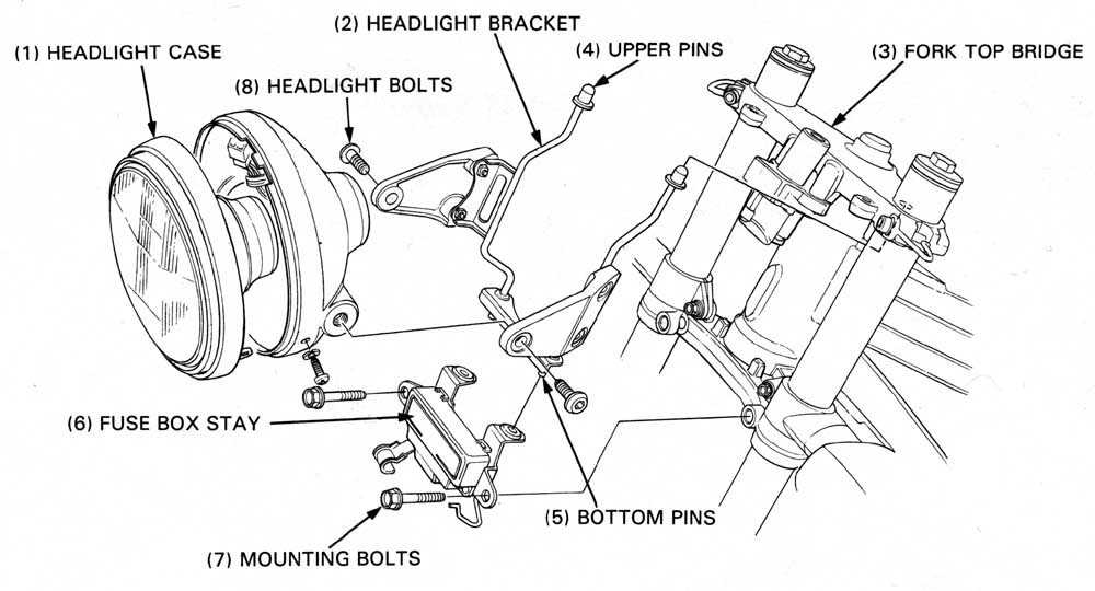
Assemble the headlight bracket and headlight case.
Insert the bracket upper pins onto the fork top bridge holes completely and hold the bracket in place.
Install the fuse box stay onto the headlight bracket bottom
pins and loosely install the mounting bolts into the steering stem.
Tighten the mounting bolts securely.
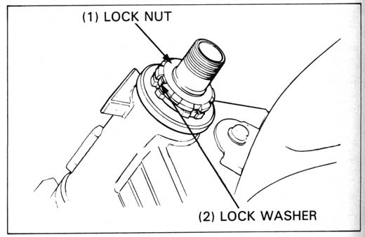
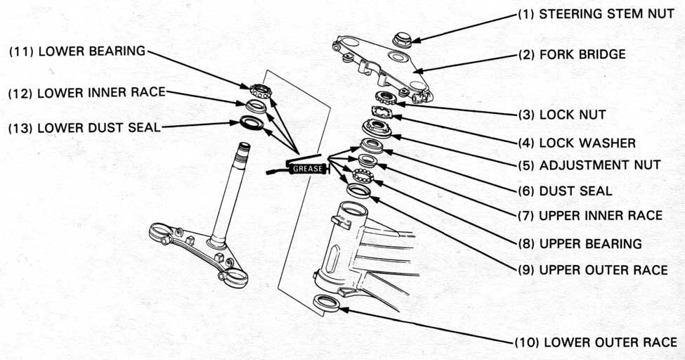
Remove the following components.
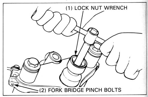
| TOOL: | |
| Lock nut wrench, 30 x 32 mm | 07716—0020400 Equivalent commercially available in U.S.A. |
Remove the fork (page 12-12).
Straighten the lock washer tabs and remove the lock nut and lock washer.
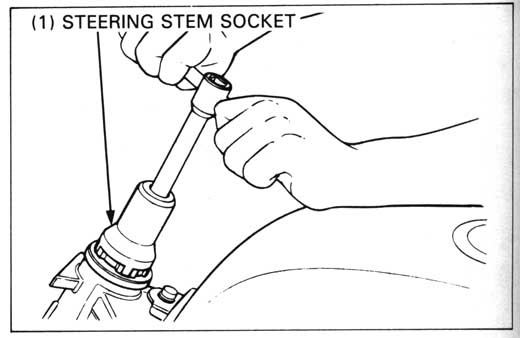
Remove the bearing adjustment nut.
| TOOL: | |
| Steering stem socket | 07916—3710100 |
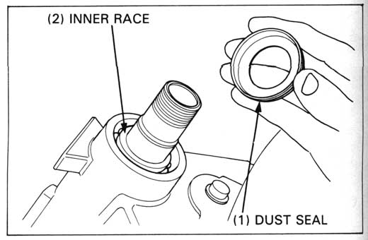
Remove the dust seal, upper bearing inner race and upper bearing pull the steering stem out of the steering head.
Check the steering stem bearings for damage or wear.
Remove the lower bearing inner race and dust seal from the steering stem.
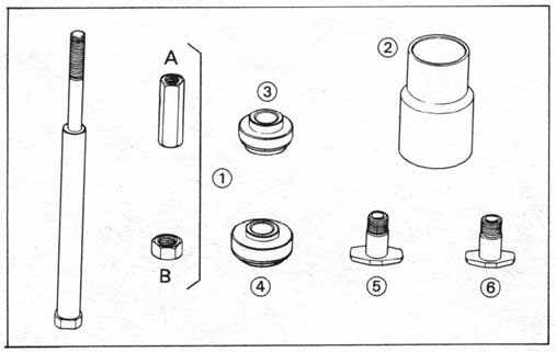
Assemble the Race Remover Set parts as shown to remove the outer races from the steering head.
| TOOLS: | |||
| BALL RACE REMOVER SET (Includes (1) to (6)) | 07946—KM90001 | ||
| (1) | DRIVER SHAFT ASSEMBLY (Includes nuts A and B) | 07946—KM90300 | |
| (2) | ASSEMBLY BASE | 07946—KM90600 | |
| (3) | DRIVER ATTACHMENT A, 47mm | 07946—KM90100 | |
| (4) | DRIVER ATTACHMENT B, 55mm | 07946—KM90200 | |
| (5) | BEARING REMOVER A, 47mm | 07946—KM90401 | |
| (6) | BEARING REMOVER B, 55mm | 07946—KM90500 | |
If the remover set is not available, use the alternate tool:
Adjustable bearing puller 07736-A01000A (U.S.A. only)
with commercially available slide hammer.
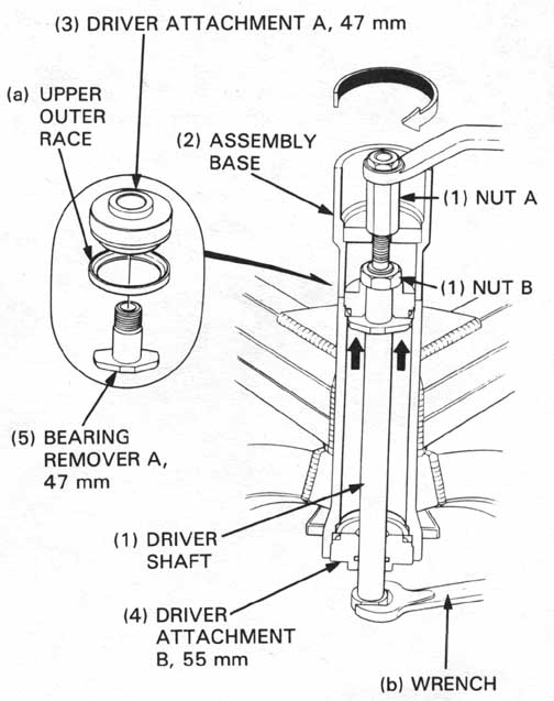
Install the ball race remover into the head pipe as shown.
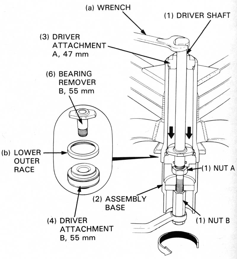
Install the bearing remover as shown and remove the lower outer race using the same procedure as for the upper outer race.
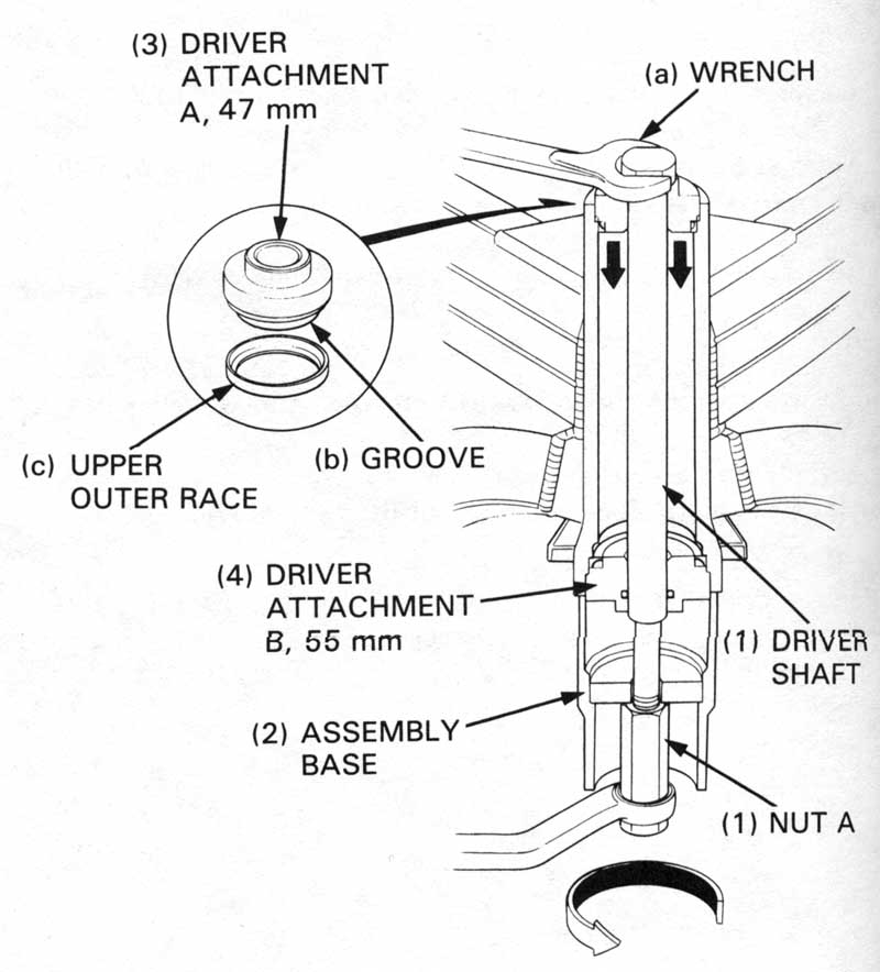
Install a new upper outer race and the ball race remover as
shown.
Holding the driver shaft ( 1 ) with a wrench, turn nut A gradually
until the groove in driver attachment A aligns with the upper
end of the steering head pipe to install the upper ball race.
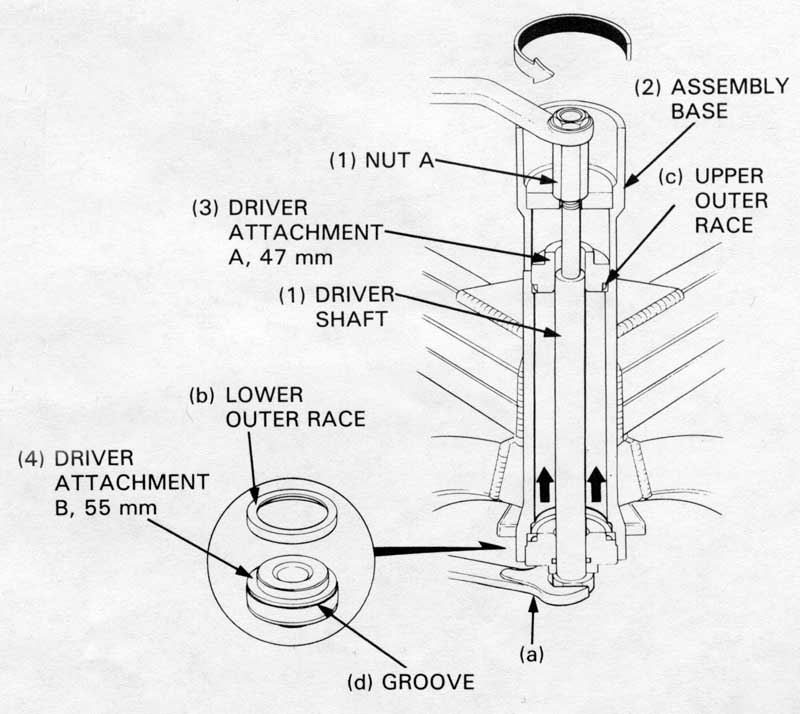
Install a new lower outer race and the ball race remover into
I the head pipe as shown.
I Holding the driver shaft (1) with a wrench, turn nut A gradually
until the groove in driver attachment B aligns with the lower
end of the steering head pipe to install the lower outer race.
(1) DRIVERSHAFT, NUT A
(2) ASSEMBLY BASE
(3) DRIVER ATTACHMENT A, 47 mm
(4) DRIVER ATTACHMENT B, 55 mm
(a) WRENCH
(b) LOWER OUTER RACE
(c) UPPER OUTER RACE
(d) GROOVE
If the remover set is not available, use the alternate tools:
| Attachment, 42 x 47 mm | 07746-0010300 |
| Attachment, 52 x 55 mm | 07746-0010400 |
| Driver | 07749-0010000 |
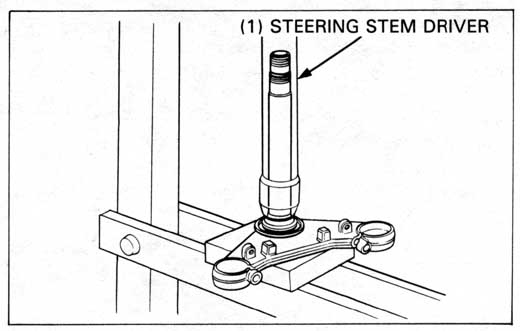
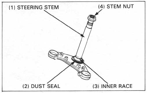
Install a dust seal onto the steering stem and press the lower bearing inner race over the stem with the special tool.
| TOOL: | |
| Steering stem driver: | 07946—MBO0000 |
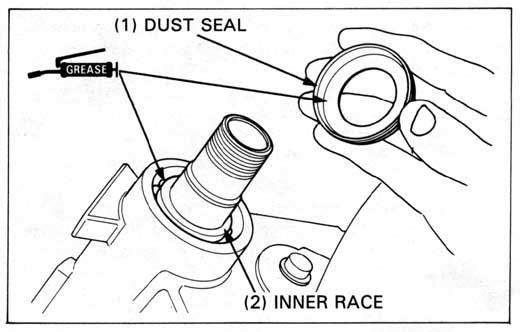
Pack the bearing cavities with clean grease.
Install the lower bearing onto the steering stem, then insert the steering stem into the steering head.
Install the upper bearing, upper bearing inner race and dust seal.
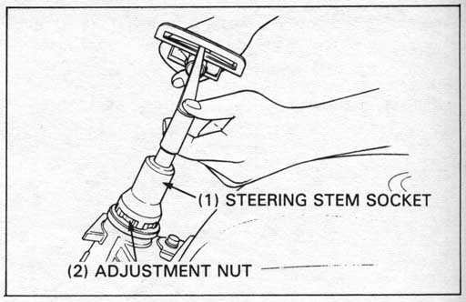
Install and tighten the adjustment nut to the specified torque.
TORQUE: 20 N•m (2.0 kg-m, 14 ft-lb)
| TOOL: | |
| Steering stem socket | 07916—3710100 |
Turn the steering stem lock-to-lock 4 or 5 times to seat the bearings, then tighten the nut to the same torque.
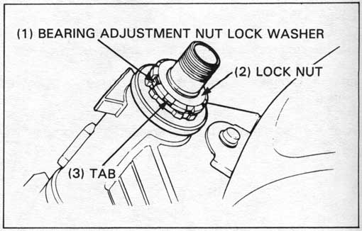
Install a new bearing adjustment nut lock washer aligning the tabs with the grooves in the nut. Bend two opposite tabs down into the grooves.
Finger tighten the lock nut all the way.
Hold the adjustment nut and further tighten the lock nut (within
90 degrees) enough to align its grooves with the lock
washer tabs.
Bend the lock washer tabs up into the lock nut grooves.
Install the fork top bridge and install the steering stem nut.
Temporarily install the fork legs.
Tighten the steering stem nut.
TORQUE: 105 N•m (10.5 kg-m, 76 ft-lb)
Tighten the bridge pinch bolts.
TORQUE: 11 N•m (1.1 kg-m, 8 ft-lb)
| TOOL: | |
| Lock nut wrench, 30 x 32 mm | 07716—0020400 Equivalent commercially available in U.S.A. |
Tighten the fork bottom pinch bolts.
TORQUE: 50 N•m (5.0 kg-m, 36 ft-lb)
Install the steering stem nut cap onto the stem nut.
Install the front wheel (page 12-12).
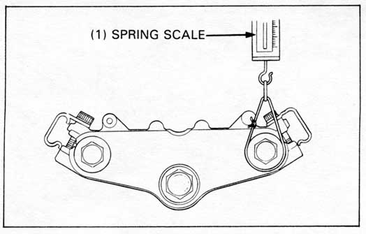
Place a stand under the engine and raise the front wheel off
the ground.
Position the steering stem in the straight ahead position.
Hook a spring scale to the fork tube and measure the steering
bead bearing preload.
The preload should be within 1.0 - 1.5 kg (2.2 - 3.3 lb) for
right and left turns.
If the readings do not fall within the range, lower the front
wheel and adjust the bearing adjustment nut.
After making sure the bearing preload is acceptable, install the
removed parts in the reverse order of removal.