really big verson
Hawkworks.net main page
Manual main index
| SERVICE INFORMATION | 7-1 |
| TROUBLESHOOTING | 7-2 |
| RIGHT CRANKCASE COVER REMOVAL | 7-3 |
| CLUTCH REMOVAL | 7-4 |
| GEARSHIFT LINKAGE | 7-8 |
| PRIMARY DRIVE GEAR | 7-10 |
| CLUTCH INSTALLATION | 7-11 |
| RIGHT CRANKCASE COVER INSTALLATION | 7-14 |
Unit: mm (in)
| ITEM | STANDARD | SERVICE LIMIT | ||
|---|---|---|---|---|
| Clutch | Spring free length | 44.4 (1.75) | 42.8 (1.69) | |
| Spring preload/length | 22.75/26.2 kg/mm (50.15/1.031 lb/in) | --- | ||
| Disk Thickness | Disk A | 2.92-3.08 (0.115-0.121) | 2.60 (0.102) | |
| Disk B | 2.62-2.78 (0.103-0.109) | 2.30 (0.091) | ||
| Plate Warpage | --- | 0.30 (0.012) | ||
| Outer guide | I.D. | 21.991-22.016 (0.8658-0.8668) | 22.09 (0.870) | |
| O.D. | 31.959-31.975 (1.2582-1.2589) | 31.92 (1.257) | ||
| Outer I.D. | 32.000-32.025 (1.2598-1.2608) | 32.10 (1.264) | ||
| Oil pump drive sprocked I.D. | 32.000-32.025 (1.2598-1.2608) | 32.10 (1.264) | ||
| Mainshaft O.D at clutch outer guide | 21.967-21.980 (0.8648-0.8654) | 21.92 (0.863) | ||
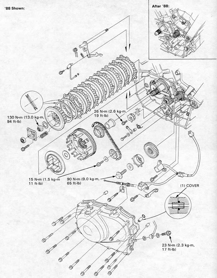
| Shift drum stopper plate bolt | 26 N•m (2.6 kg-m, 19 ft-lb) Apply locking agent to the threads |
| Primary drive gear bolt | 90 N•m (9.0 kg-m, 65 ft-lb) |
| Oil pump driven sprocket bolt | 15 N•m (1.5 kg-m, 11 ft-lb) Apply locking agent to the threads |
| Cluch lock nut | 130 N•m (13.0 kg-m, 94 ft-lb) Staked nut |
| Oil pass pipe bolt (8 mm) (7 mm) | 23 N•m (2.3 kg-m, 17 ft-lb) 10 N•m (1.0 kg-m, 7.2 ft-lb) |
Faulty clutch operation can usually be corrected by adjusting the clutch lever free play.
Clutch slips when accellerating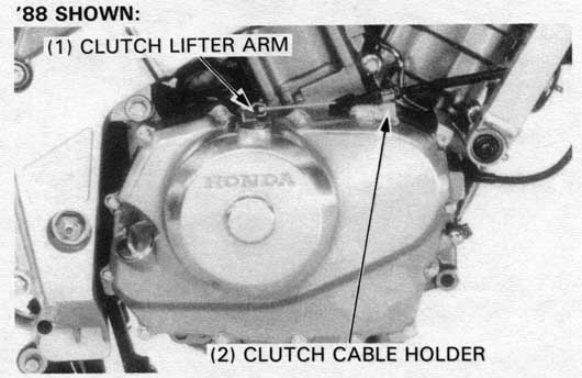
Drain the engine oil (page 2-3).
Remove the exhaust pipe.
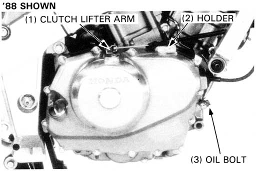
Remove the clutch cable holder and disconnect the clutch cable
from the clutch lifter arm.
Loosen the oil pipe holder and remove the oil pipe bolt
and sealing washers from the right crankcase cover.
Remove the right crankcase cover bolts and cover.

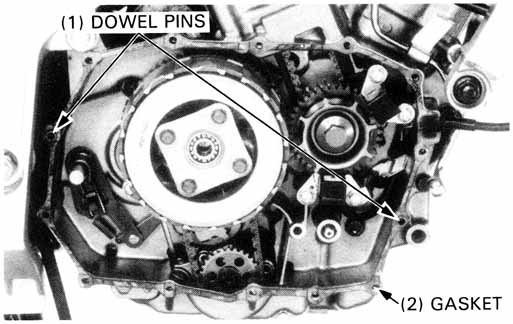
Remove the dowel pins and gasket.
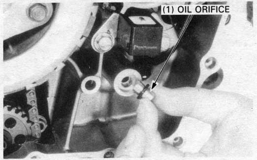
Remove the oil orifice.
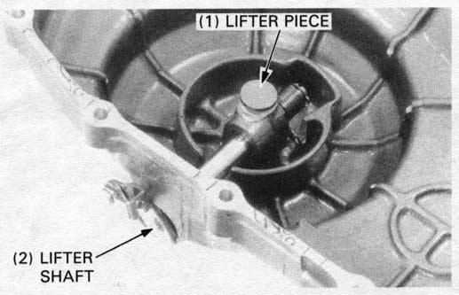
Remove the clutch lifter piece, and remove the snap ring and return spring from the right crankcase cover.
Remove the clutch lifter shaft.
Check the clutch lifter piece and shaft for damage or excessive
scratching.
Check the return spring for fatigue or damage.
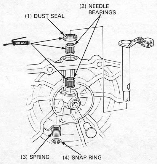
Check the needle bearings for wear or damage or a loose
fit in the cover.
Check the dust seal for fatigue or damage.
Apply grease to the dust seal and needle bearing.
Install the clutch lifter shaft, snap ring and return spring.
Hook the spring end in the cover tab securely, and turn
the shaft.
Install the clutch lifter piece, aligning the piece end with the groove in the clutch lifter shaft.
Remove the following:
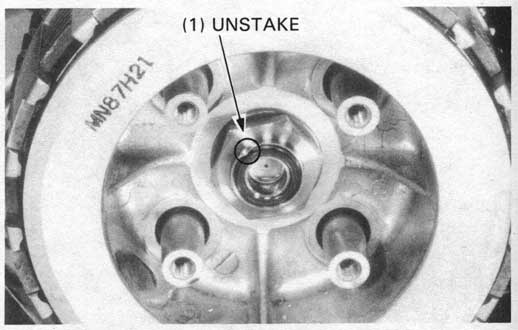
Unstake the clutch lock nut with a drill or grinder.
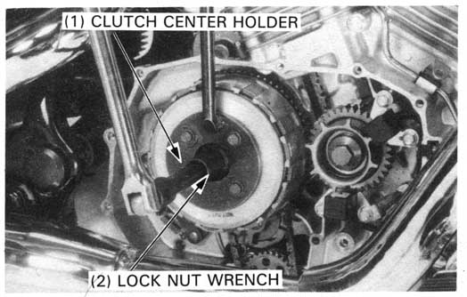
Hold the clutch center with the special tool and loosen the clutch lock nut. Remove the tools and the lock nut.
| TOOLS: | |
| Clutch center holder | 07923—KE10000 or 07HGB—001000A (U.S.A. only) |
| Lock nut wrench, 17 x 27 mm | 07716—0020300 Equivalent commercially available in U.S.A. |
HINT: A conventional 27 mm socket works as a lock nut wrench.
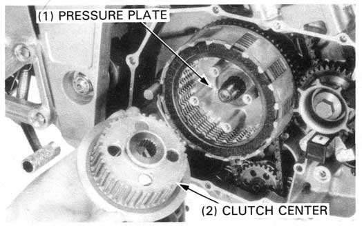
Remove the following:
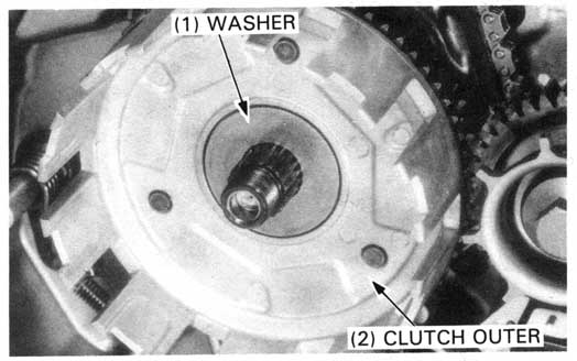
Remove the thrust washer and clutch outer.
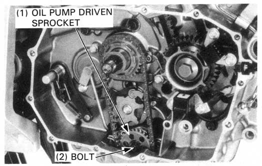
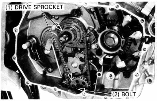
Remove the oil pump driven sprocket mounting bolt, driven sprocket and oil pump drive chain.
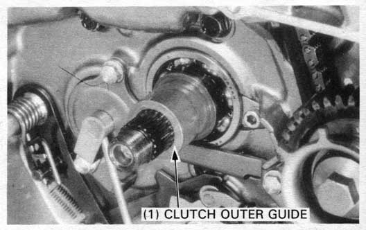
Remove the drive sprocket and clutch outer guide from the mainshaft.
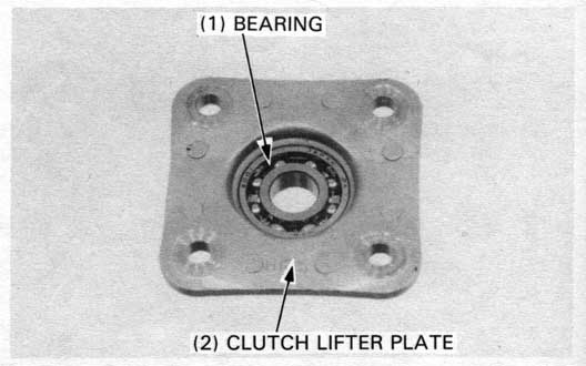
Check the lifter plate bearing for damage.
Turn the bearing inner race with your finger.
The bearing should turn smoothly and quietly.
Also check that the bearing outer race fits tightly
in the clutch lifter plate.
Replace the bearing if necessary.
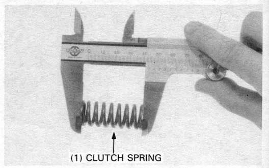
Measure the spring free length.
SERVICE LIMIT: 42.8 mm (1.69 in)
Info:The standard length is 44.4 mm (1.75 in).
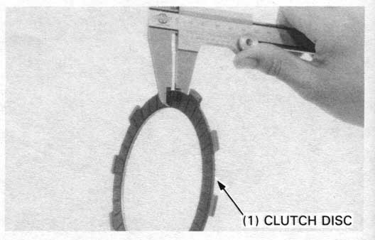
Replace the clutch discs if they show signs of scoring
or discoloration.
Measure the thickness of discs A and B.
| SERVICE LIMITS:< | ||
| Disc A: | 2.60 mm (0.102 in) | |
| Disc B: | 2.30 mm (0.091 in) | |
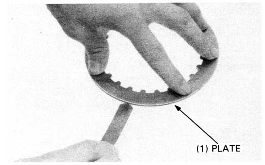
Check the plate warpage on a surface plate using a thickness gauge.
SERVICE LIMIT: 0.30 mm (0.012 in)
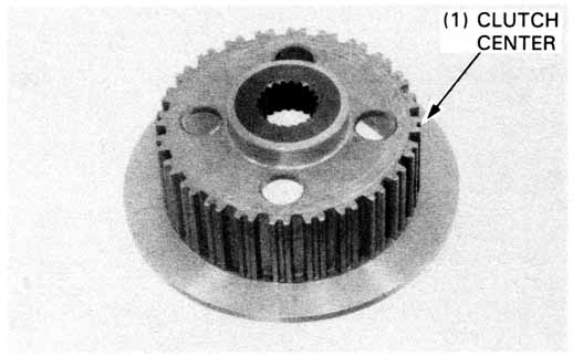
Check the clutch center for nicks or indentations made by the clutch plates.
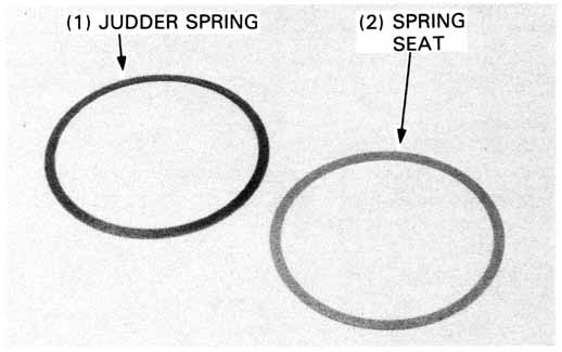
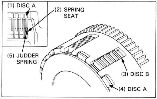
Check the spring seat and judder spring for distortion, wear or damage.
Replace them if necessary.
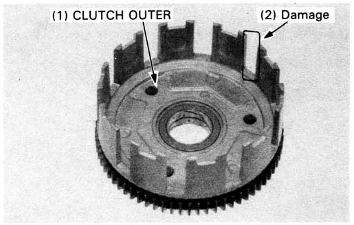
Check the slots in the clutch outer for nicks or indentations made by the clutch discs.
Measure the l.D. of the clutch outer.
SERVICE LIMIT: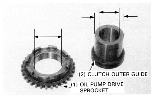
| Oil pump drive sprocket l.D. | 32.10 mm (1.264 in) |
| Clutch outer guide O.D. | 31.92 mm (1.257 in) |
| I.D. | 22.09 mm (0.870 in) |
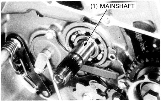
Measure the mainshaft O.D. at the clutch outer guide.
SERVICE LIMIT: 21.92 mm (0.863 in)
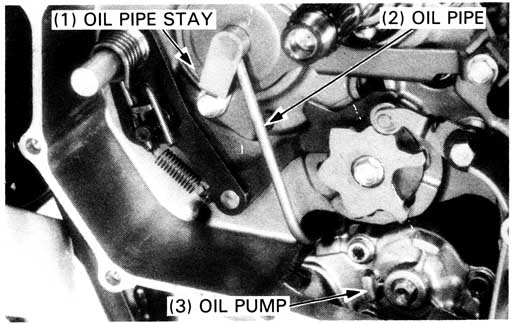 Loosen the two oil pipe stay mounting bolts and remove the oil
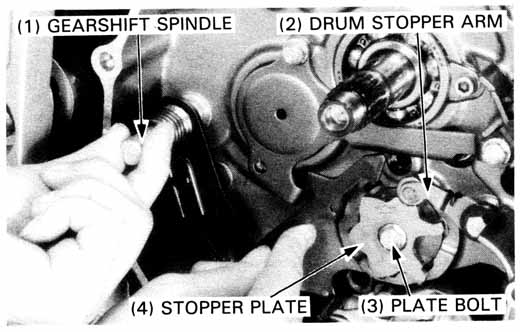
Remove the following:
Install the collar, spring, stopper arm,
washer and stopper arm bolt and tighten the bolt.
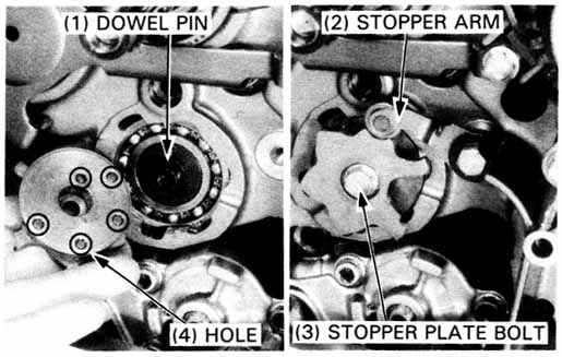
Install the dowel pins into the holes of the gearshift drum.
Lift up the drum stopper arm and install the drum stopper plate.
Apply locking agent to the threads of the stopper plate bolt and tighten the bolt.
TORQUE: 26 N•m (2.6 kg-m, 19 ft-lb)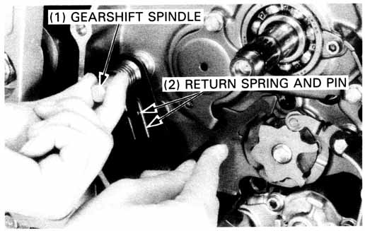
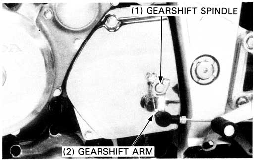
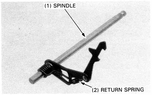
Install the gearshift spindle, aligning the return spring ends with the pin in the case.
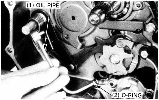
Install the oil pipe with a new O-ring onto the oil pipe stay and oil pump.
Tighten the bolts securely.
Install the removed parts in the reverse order of removal.
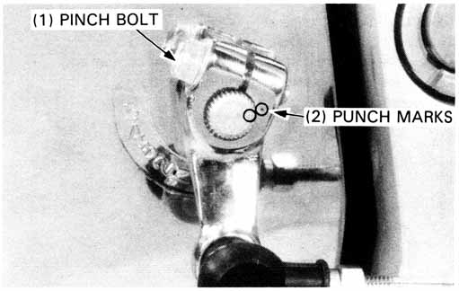
Install the gearshift arm to the gearshift spindle.
Align the punch mark on the arm with the punch mark on the spindle.
Tighten the gearshift arm pinch bolt.
TORQUE: 12 N•m (1.2 kg-m, 9 ft-lb)
Install the drive sprocket cover.
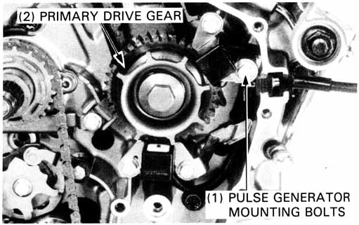
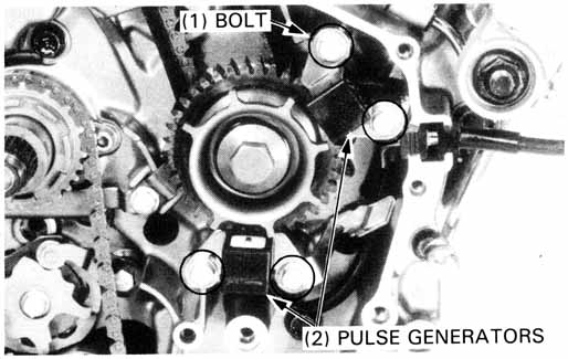
Remove the following:
Remove the pulse generator mounting bolts and pulse generators.
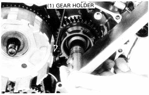
Temporarily install the clutch outer,
then install the gear holder as shown.
| TOOL: | |
| Gear holder | 07724—0010100 |
| Not available in U.S.A. |
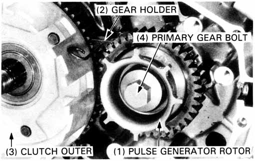
Remove the following:
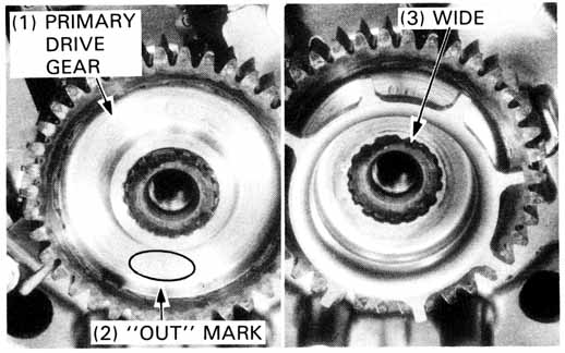
Install the primary drive gear with the "OUT" mark facing out.
Install the pulse generator rotor.
Temporarily install the clutch outer and install the gear holder as shown.
| TOOL: | |
| Gear holder | 07724—0010100 Not available in U.S.A. |
Install the washer and bolt and tighten the bolt.
TORQUE: 90 N•m (9.0 kg-m, 65 ft-lb)
Remove the gear holder and clutch outer.
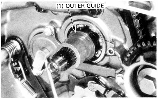
Apply MoS2 paste grease to the outside of the clutch outer guide and install the oil pump drive sprocket over the outer guide.
Install the oil pump drive chain on the drive sprocket.
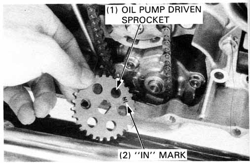
Install the oil pump driven sprocket with the "IN" mark facing inside.
Guide the drive chain over the sprocket.
Apply locking agent to the threads of the driven sprocket mounting bolt and tighten it with the washer to the specified torque.
TORQUE: 15 N•m (1.5 kg-m, 11 ft-lb)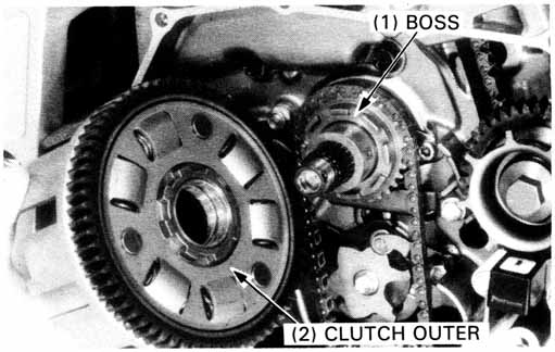
Align the grooves in the clutch outer with the bosses on the oil pump drive sprocket while turning the sprocket with the chain and pushing the clutch outer onto the shaft.
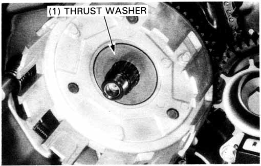
Install the thrust washer onto the mainshaft.
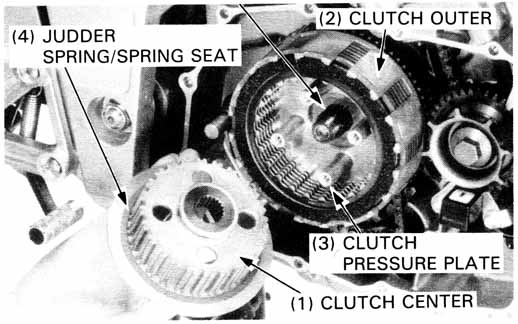
Install the pressure plate, clutch discs B, plates and disc A in the clutch outer.
Install the spring seat and judder spring on the clutch center as shown.
Install them in the clutch outer.
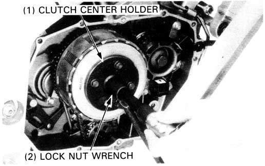
Hold the clutch center with the clutch center holder, and tighten the lock nut to the specified torque.
| TOOLS: | |
| Clutch center holder | 07923—KE10000 or 07HGB—001000A (U.S.A. only) |
| Lock nut wrench, 17 x 27 mm | 07716—0020300 Equivalent commercially available in U.S.A. |
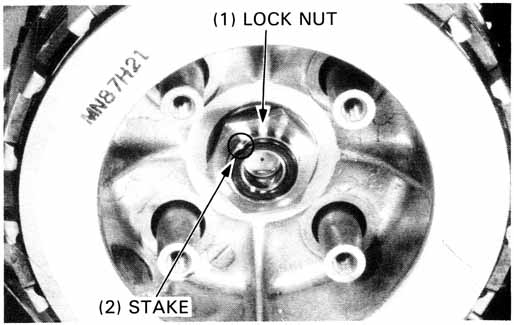
Stake the lock nut with a center punch.
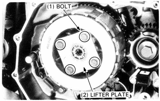
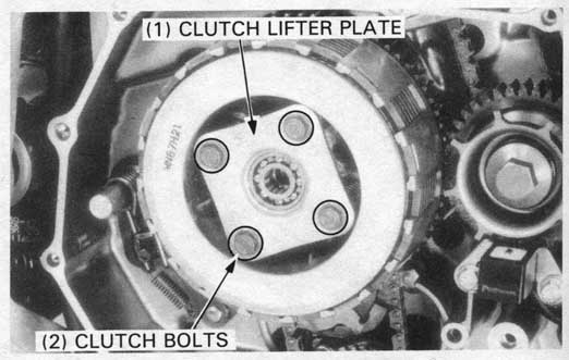
Install the clutch springs, lifter plate and bolts.
Tighten the bolts in a crisscross pattern in 2 or 3 steps.
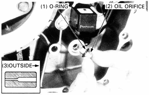
Check the oil orifice for clogging.
Install a new O-ring on the oil orifice.
Install the oil orifice with its smaller hole facing in.
Info: Gasket part number is 11394-MV1-850, about $10.50
Tighten the right crankcase cover mounting bolts in a crisscross pattern in 2 or 3 steps and install the clutch cable holder and oil pipe holder at the same time.
Info: TORQUE: 9 N•m (0.9 kg-m, 6.5 ft-lb)
Connect the clutch cable to the clutch lifter arm.| TORQUE: | |
| Exhaust pipe joint nut: | 27 N•m (2.7 kg-m, 20 ft-lb) |
| Muffler band bolt: | 27 N•m (2.7 kg-m, 20 ft-lb) |