really big verson
Hawkworks.net main page
Manual main index
| SERVICE INFORMATION | 5-1 |
| TROUBLESHOOTING | 5-1 |
| SYSTEM TESTING | 5-2 |
| COOLANT REPLACEMENT | 5-3 |
| THERMOSTAT | 5-3 |
| RADIATOR/COOLING FAN | 5-5 |
| WATER PUMP | 5-7 |
| ITEM | SPECIFICATIONS |
|---|---|
| Radiator cap relief pressure | 88 - 127 kPa (0.9 - 1.3 kg/cm2, 13 - 18 psi) |
| Freezing point (Hydrometer test): | 55% Distilled water + 45% ethylene glycol: -32°C (-25°F) 50% Distilled water + 50% ethylene glycol: -37°C (-34°F) 45% Distilled water + 55% ethylene glycol: -44.5°C (-48°F) |
| Coolant capacity: Coolant change: Total system: | 1.60 lit (1.51 US qt, 1.28 Imp qt) 2.20 lit (2.32 US qt, 1.94 Imp qt) |
| Thermostat | Begins to open: 80° to 84°C (176° to 183°F) Valve lift: Minimum of 8 mm at 95°C (0.3 in at 203°F) |
| Boiling point (with 50 - 50 mixture): | Unpressurized: 107.7°C (226°F) Cap on, pressurized: 125.6°C (258°F) |
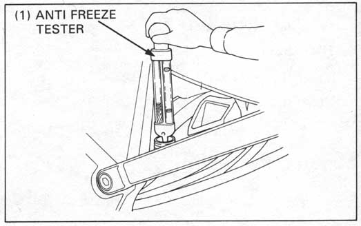
Remove the reserve tank cap.
Test the coolant mixture with an antifreeze tester.
For maximum corrosion protection, a 50 - 50% solution of
ethylene glycol and distilled water is recommended.
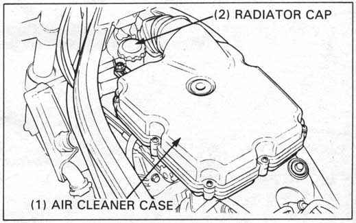
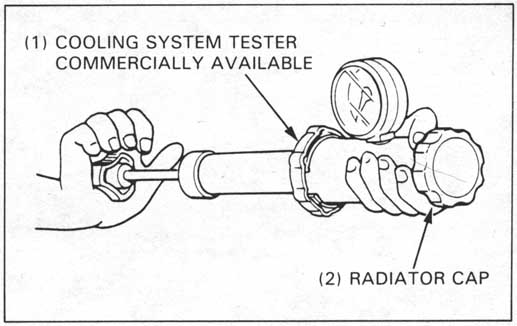
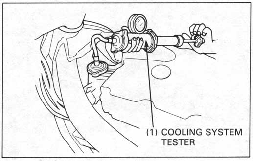
Wet the radiator cap sealing surface, install the cap on the tester, and apply pressure.
Replace the radiator cap if it does not hold pressure, or if it’s relief pressure is too high or too low. It must hold specified pressure for at least six seconds.
RADIATOR CAP RELIEF PRESSURE:
88 - 127 kPa (0.9 - 1.3 kg/cm2, 13 - 18 psi)
Remove the fuel tank and radiator cap.
Attach the tester to the radiator and apply enough pressure to test the radiator, engine and hoses, check for leaks.
Repair or replace components if the system will not hold specified pressure for at least six seconds.
Remove the radiator cap (page 5-2).
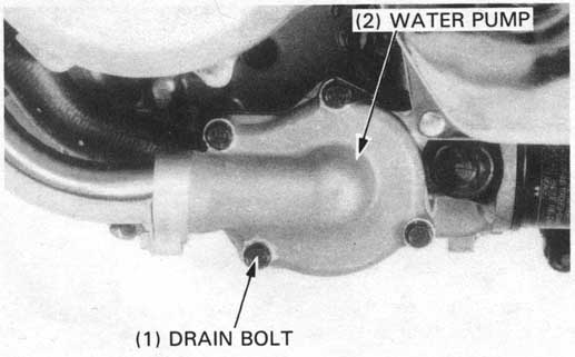
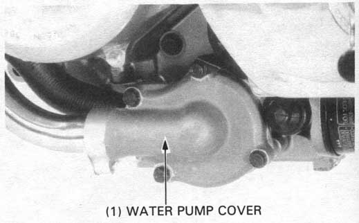
Drain the coolant from the system by removing the
drain bolt on the water pump cover.
Reinstall the drain bolt.
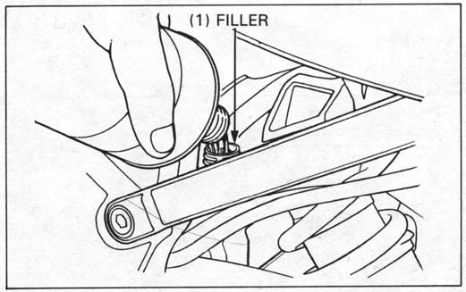
Fill the system with 50 - 50 mixture of distilled water
and ethylene glycol.
Bleed air from the cooling system.
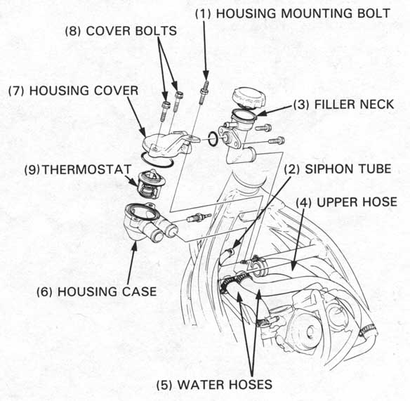
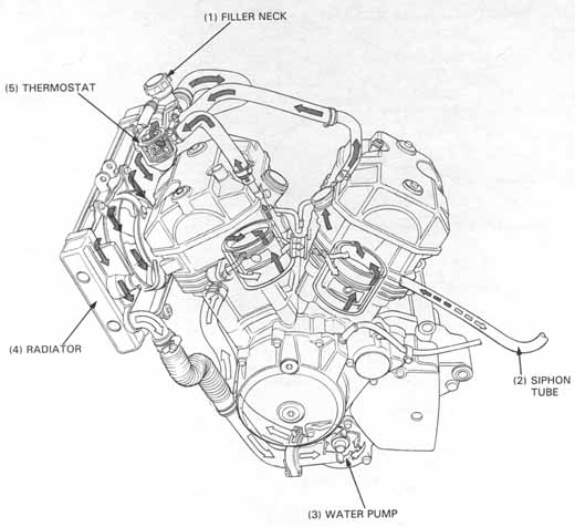
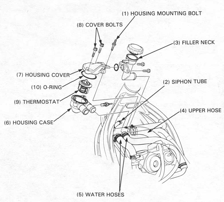
Remove the following:
Remove the thermostat housing mounting bolts.
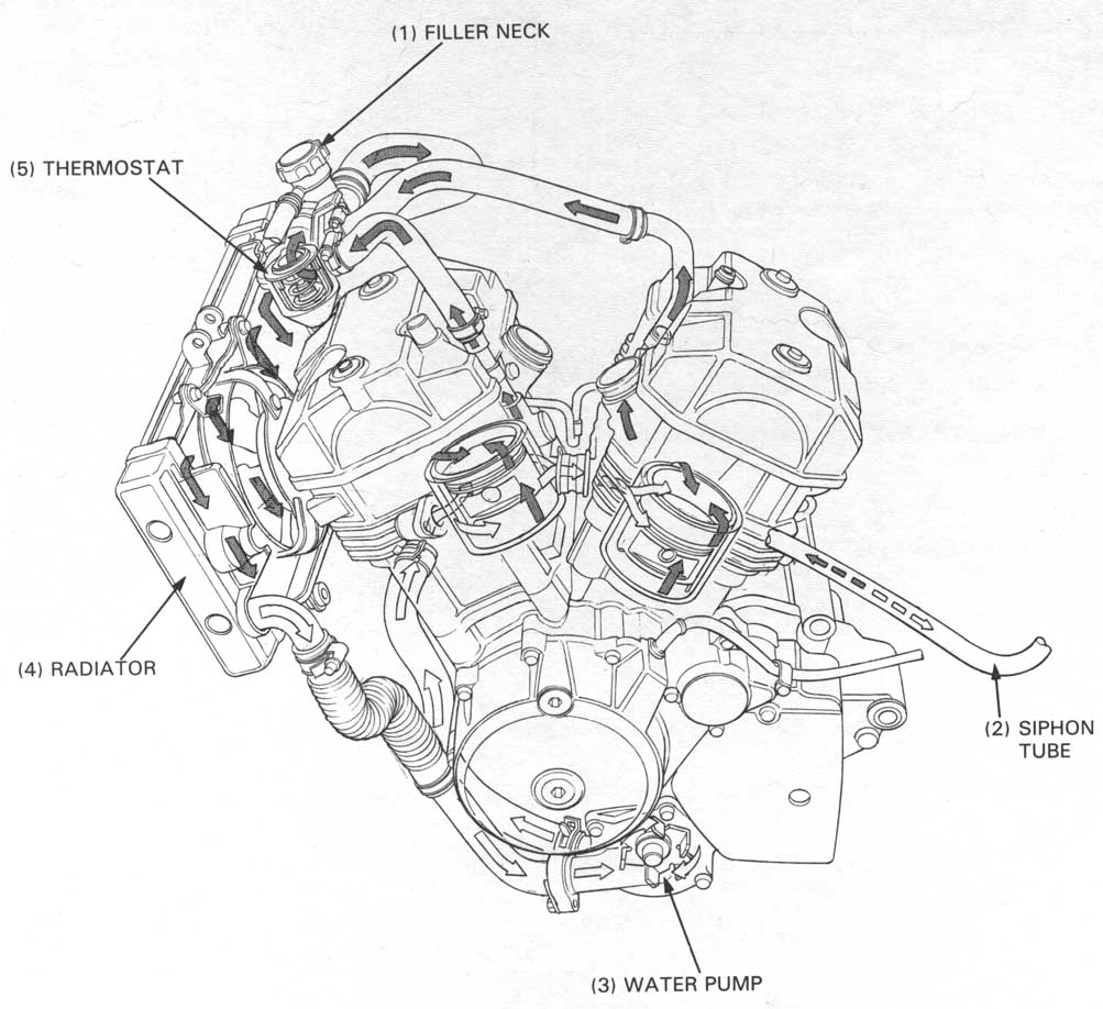
Disconnect the siphon tube from the filler neck.
Disconnect the upper radiator hose at the filler neck
and the water hoses at the thermostat housing.
Remove the thermostat housing case and filler neck from
the frame.
Remove the housing cover attaching bolts and separate
the case from the cover.
Remove the thermostat from the housing case.
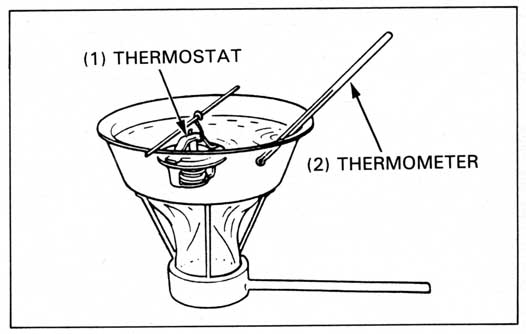
Inspect the thermostat visually for damage.
Suspend the thermostat in heated water to check its operation.
Replace thermostat if valve stays open at room temperature, or if it responds at temperatures other than those specified.
Data:
| Start to open | 80° to 84°C (176 - 183°F) |
| Valve lift | 8 mm (0.3 in) minimum when heated to 95°C (203°F) for five minutes. |
Install the following:
Assemble the case and filler neck with the new O-ring.
Tighten the bolts.
Install the thermostat housing case and filler neck onto the frame.
Connect the removed hoses and tube securely.
Install the removed parts in the reverse order of removal.
Fill the system with coolant and air bleed it.
Drain the coolant (page 5-3).
Disconnect the cooling fan motor connector.
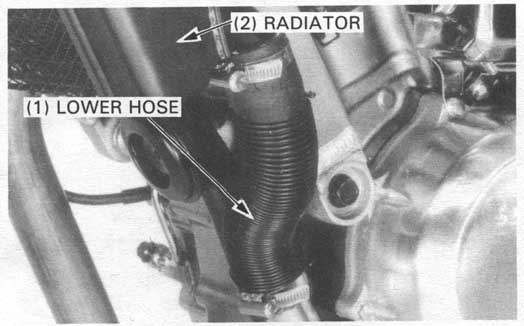
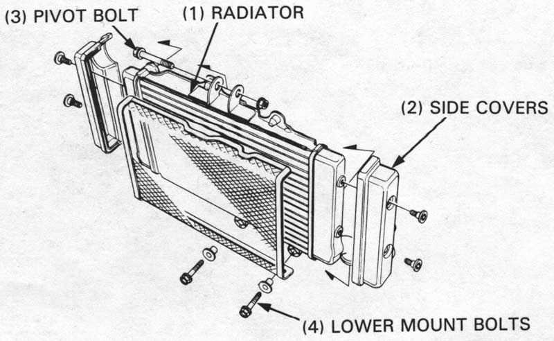
Disconnect the lower radiator hose at the radiator.
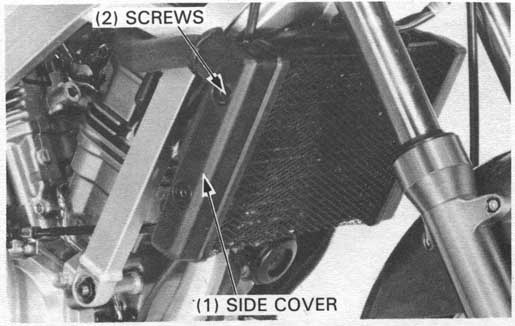
Remove the radiator side covers by removing mounting screws.
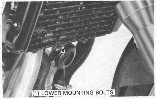
Remove the radiator lower mounting bolts.
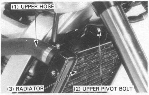
Disconnect the upper radiator hose at the radiator. Remove the radiator upper pivot bolt and radiator from the frame.
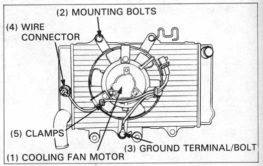
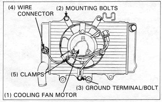
Disconnect the cooling fan motor wire connector from the thermostatic
switch and remove the wire from the clamp.
Remove the ground wire terminal bolt.
Remove the cooling fan motor mounting bolts and cooling fan motor.
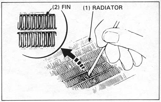
Inspect the radiator soldered joints and seams for leaks.
Blow dirt out from between core fins with compressed air. If insects, etc., are clogging the radiator, wash them off with low pressure water.
Carefully straighten any bent fins.
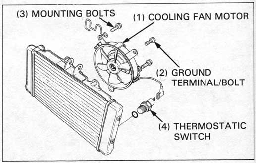
Install the cooling fan motor.
Connect the ground terminal and thermostatic switch wire connector.
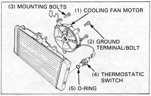
Install the mounting bolts.
If the thermostatic switch was removed, install a new O-ring and tighten to the specified torque.
THERMOSTATIC SWITCH:
TORQUE: 18 N•m (1.8 kg-m, 13 ft-lb)
Install the radiator in the reverse order of removal.
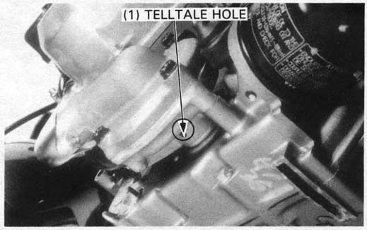
Inspect the telltale hole for signs of mechanical seal coolant leakage.
Replace the water pump as an assembly if the mechanical seal is leaking.
Drain the engine oil (page 2-3).
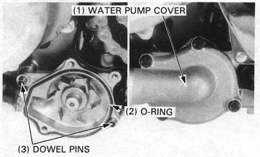
Remove the water pump cover mounting bolts and cover.
Remove the O-ring and dowel pins from the water pump assembly and disconnect the water hose.
Remove the water pump from the crankcase.

Check the water pump for mechanical seal leakage and bearing deterioration. Replace the water pump as an assembly if necessary.
Connect the water hose with the clamp.
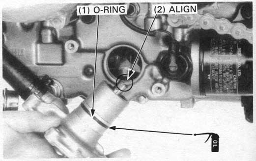
Apply a coat of clean engine oil to a new O-ring and install it in the
water pump shaft housing groove.
Align the water pump shaft groove with the oil pump shaft and insert the water pump into the crankcase.
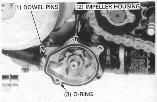
Apply a coat of engine oil to a new O-ring and install it around the impeller housing.
Install the two dowel pins.